
This paper describes the design, testing, installation, and performance of the first fully completed well using an intelligent inner completion inside an uncemented liner with openhole packers for zonal isolation. The term “fully completed” implies full reservoir access along the pay length for production and high-rate matrix acid stimulation using limited entry for fluid diversion within well segments. The well-design concept evolved from technical challenges associated with completing long cased-and-cemented laterals in the mature Ekofisk waterflood.
Introduction
To improve acid stimulation and reduce casing deformation and well failures in the Ekofisk field, a new class of wells was introduced to the field (please see the complete paper for a discussion of field characteristics and associated challenges). These new fully completed wells were perforated along the entire horizontal section and used limited-entry techniques to distribute acid more evenly over the reservoir intervals. Perforations were generally spaced at one hole every 10 ft of reservoir net pay along the horizontal section, with stimulation volumes on the order of 20 bbl of 28% hydrochloric acid (HCl) per perforation. These new completion techniques proved successful in providing high-productivity completions with low well-failure rates. Post-stimulation skin values have been found to be in the –4 to –4.5 range, while liner deformation and well failures have decreased.
The new fully completed designs were first implemented in horizontal wells with cemented liners, but as confidence in the designs increased, conceptual planning moved to openhole designs with uncemented liners. To improve the fully completed well designs further, it was desired to combine the benefits of a surface-operated intelligent-well system (IWS) for downhole flow control with limited-entry diversion to provide uniform acid distribution along pay intervals in an uncemented liner. This led to the Ekofisk 2/4-B-19C (hereafter referred to as the B-19C) well design. For a discussion of the functional requirements, design features, and modeling and testing of the uncemented-liner completion and all of its components, please see the complete paper.
Operational Highlights
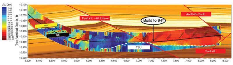
The complex nature of the naturally fractured chalk in the Ekofisk field makes it challenging to predict the pattern of the waterflood, leaving the details of the final completion to be decided only after the well has been drilled. A sophisticated logging plan was implemented to characterize the wellbore better and improve hole-conditioning efforts. Among the logging-while-drilling (LWD) tools used was a deep directional electromagnetic (DDEM) tool, which helped with trajectory planning while drilling. Approximately halfway into the Tor formation, the DDEM readings indicated that the well was being drilled into the lower, wet layers of the target Upper Tor formation near the border of deeper Tor layers. After passing through a fault, higher resistivity values were seen above the well and the decision was made to increase the hole angle from 90 to 94°, steering up and into an oil-filled formation. The presence of subseismic faults and layers with high water saturations also plays an important role in the decision on where to blank off sections with openhole packers and solid liner joints vs. where to expose the liner to the reservoir by use of acid-soluble plugs. Fig. 1 shows the point at which the decision was made to build to 94° in an effort to remain in the oil-saturated Tor interval.
Formation-pressure points in the shallower Ekofisk formation, at the heel of the horizontal well, revealed lower-than-expected reservoir pressures. Anticipating higher pressure in the deeper Tor formation, lost-circulation-material and wellbore-strengthening techniques were used to manage mud losses to the low-pressured heel interval. Drilling concluded 500 ft shallower than planned because of increasing formation pressure and water saturation. Maximum pressure differential across the reservoir had increased to 1,600 psi, which would make cementing the liner very challenging. LWD data indicated five pay zones of 1,400 ft and four water-saturated intervals, making zonal isolation absolutely critical for long-term production. In terms of the basis of design, the B-19C well was an ideal candidate to field trial the uncemented-liner technology for its capability to provide zonal isolation. A five-zone completion was selected with two openhole packers between each adjacent interval for zonal isolation in the open hole.
The 7⅝-in.-uncemented-liner makeup and running operation went well until the last 800 ft from total depth (TD), where sticking occurred and the string was worked in order to reach TD.
After the 7⅝-in. liner was run to TD and the liner hanger was set successfully, a retrievable, hook-wall service packer was run and set immediately below the liner hanger for pressure setting all openhole equipment. A leak developed at 8,200 psi while attempting to pressurize the liner and prevented reaching the designed 10,000-psi setting pressure for the openhole packers. The service packer was then reset at different depths, and the liner leak was located near an openhole packer at the top of Zone B. An injection test with mud indicated that the size of the leak matched the flow area of the openhole-packer setting ports. Before retrieving the service packer, it was used to pressure set all liner components below the leak with 10,000 psi. A cup-type straddle-packer assembly was then run per the contingency plan and proved successful in setting all 17 remaining pressure-activated liner components located above the leak.
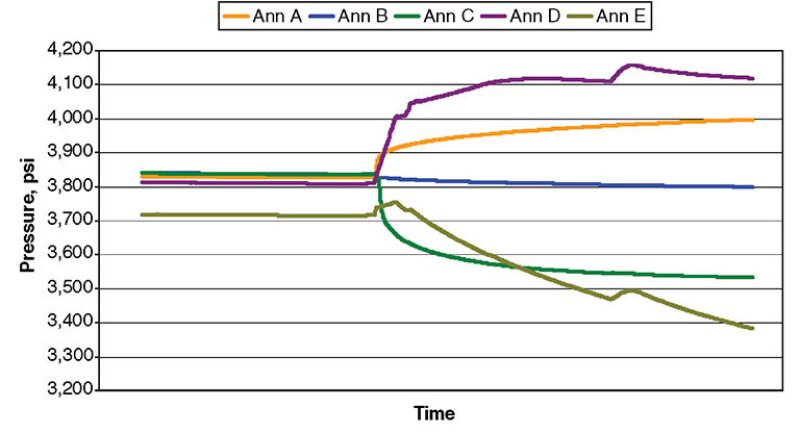
A five-zone IWS inner string was then installed successfully with full functionality of hydraulically controlled valves, mechanical isolation packers, and pressure and temperature gauges for each interval. The isolation packers were set, and, as expected, the pressure in each zone diverged from equilibrium to approach the respective-interval reservoir pressure (Fig. 2). This implied that every stage contained some aluminum plugs already dissolved by the 15% HCl. It also confirmed the status of positive zonal isolation in the open hole.
Acid-Stimulation Results
After moving the rig off location, lines were laid to the well and a dedicated stimulation vessel moved into position for the acid treatment. B-19C encountered a number of oil and water intervals. After reviewing the LWD data, the completion liner was set up to stimulate five oil zones and to isolate wet zones with openhole packers.
Each completion interval (A, B, C, D, and E) was equipped with an IWS assembly consisting of a surface-controlled valve, providing flow access to the formation, and pressure and temperature gauges ported to tubing and annulus (Fig. 3). Each zone was stimulated selectively, starting from Zone E (heel zone) to Zone A (toe zone), by use of the IWS flow-control valves. For each treatment, the IWS valve in the treatment zone was opened. Tubing pressure was then increased to break the rupture disks in the automatic control valves (ACVs), allowing fluid displacement to the target interval. The initial fresh water filling the tubing was followed by a 15% HCl/mutual-solvent mixture pumped at low rate (Fig. 3b).
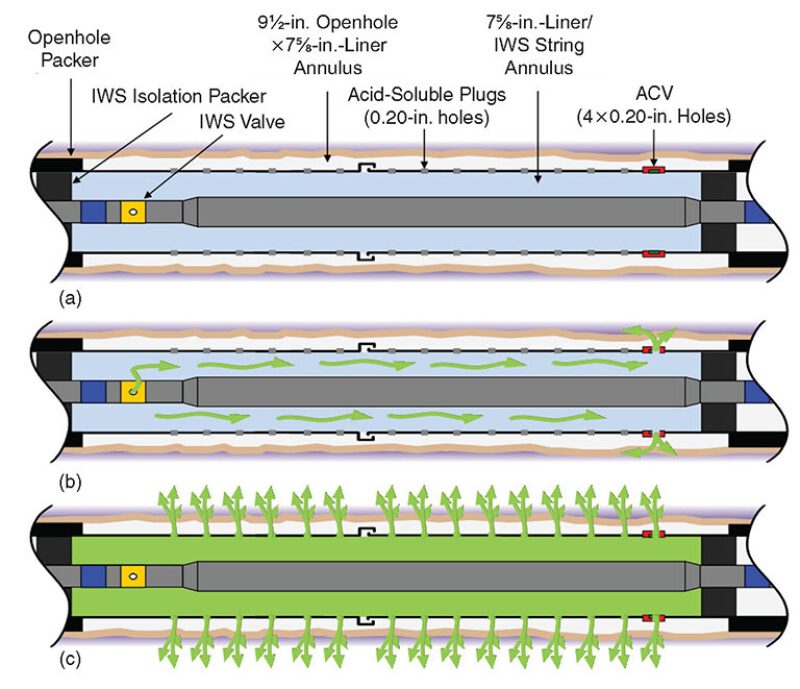
Acid pumping continued until the entire 7⅝-in.-liner/IWS-string annulus had been displaced to acid. This placed the 15% HCl/mutual-solvent system in direct contact with the acid-soluble plugs (ASPs) that sealed the holes in the 7⅝-in. liner and isolated the formation. The ASPs were then soaked for a few hours, depending on the downhole temperature, while leakoff was monitored to determine the rate of plug dissolution. The HCl/mutual-solvent system was then displaced with fresh water, and an injectivity test was pumped at maximum rate consistent with well-pressure limits. At the end of the injectivity period, a hard shutdown was conducted to determine the instantaneous shut-in pressure and to allow calculation of the number of, and equivalent flow area for, the dissolved ASPs. If sufficient flow area had been exposed by the acid, then the main acid treatment could proceed as planned (Fig. 3c). If the flow area was deemed insufficient to pump the main acid treatment, then another HCl/mutual-solvent treatment was pumped and another soak and injectivity step was conducted.
After dissolving the ASPs, the flow of the 28% HCl used in the main acid treatment goes through the ASP holes (Fig. 3c). The main acid treatments consisted of pumping 75 gal of 28% HCl per foot of completion interval at high rate, followed by approximately 150 gal of freshwater overflush per foot of interval. At design pump rates, downhole pressures at the reservoir face typically start out at or above formation-parting pressure and very quickly drop below fracture pressure as acid enters the chalk formation. This pressure behavior indicates that the bulk of the acid-stimulation treatment is pumped under matrix-injection conditions conducive to wormholing of the near-wellbore chalk reservoir.
All zones were stimulated successfully. Post-stimulation skins range from -4.34 to -4.95, corresponding to effective-wellbore-radius values ranging from 30 to 56 ft. These openhole-stimulation results are similar to those seen in cased-and-perforated, fully completed wells in the field.
Production Results
After conclusion of acid-treating operations, B-19C was turned over to field-production operations. The well was flowed back at increasing rates with all zones open, and, after approximately 3 months of stabilization time, a well test was conducted. The objectives of this test program were to check the mechanical function of the sleeves, determine any zone-to-zone communication, and acquire data on the rates and types of fluids flowing from the various completed intervals. The test showed that all downhole gauges were functioning as designed, allowing both annular and tubing pressure and temperature from each zone to be recorded. The test program confirmed communication between the three bottommost Tor zones (A, B, and C). It also indicated that one zone, Zone D, contributed more water than the others. After this information was obtained, Zone D was shut in to reduce the well’s water cut and lighten the fluid column.
The low water cut measured in the B-19C early flow tests also indicated that the openhole packers had withstood the high-rate acid treatment and were effectively isolating the water zones from the acid-stimulated oil zones. Review of acid-treatment data had shown some pressure/temperature communication late in the Zone C and Zone B acid treatments. Analysis of the magnitude and duration of these leaks indicated that they were small leaks; however, even a small leak while pumping acid could provide a flow path for high-pressure water during production operations. Fortunately, the well’s production data have shown that the high-pressure water zones along the horizontal section are isolated effectively.
Overall production results from the well have been encouraging. Despite lower-than-expected reservoir pressures and reservoir-net-pay length, B-19C is producing at rates above expectations. The use of an intelligent-well-completion system in this well allowed the very-low-pressure Zone E and the marginal Zone D intervals to be completed with the better intervals seen at the toe of the well. This would not have been possible with a conventional completion.
This article, written by JPT Technology Editor Chris Carpenter, contains highlights of paper SPE 166209, “Intelligent Completions and Uncemented Liners Combine To Provide a Fully Completed Solution With Zonal Isolation in Norway,” by A.W. Kent, D.W. Burkhead, R.C. Burton, K. Furui, S.C. Actis, K. Bjornen, J.J. Constantine, W.W. Gilbert, R.M. Hodge, L.B. Ledlow, M. Nozaki, A. Vasshus, and T. Zhang, ConocoPhillips, prepared for the 2013 SPE Annual Technical Conference and Exhibition, New Orleans, 30 September–2 October. The paper has not been peer reviewed.