
The great majority of wells do not pollute. With that fact in mind, the purpose of this paper is to explain basic concepts of well construction and illustrate differences between single-barrier failure in multiple-barrier well design and outright well-integrity failure that could lead to pollution, using published investigations and reviews from data sets taken from wells worldwide. Ultimately, it is clear that there is absolutely no one-size-fits-all well-failure frequency.
Introduction
For purposes of focus and brevity, this work is limited to the failure potential of the constructed barriers remaining in the producing well after drilling (e.g., casing, cement, packers, tubing, and wellheads) and of other downhole equipment that remains part of the producing well at the handover from drilling to production operations.
Well-Design Overview: Establishing Redundant Barriers
Barriers may be active, passive, or, in some cases, reactive. Active barriers such as valves can enable or prevent flow, while passive barriers are fixed structures such as casing and cement. When barriers are used in series (nested one inside the other), a multiple-barrier system is created, essentially a “defense-in-depth” barrier system. Reactive barriers are invisible or unobtrusive in normal operations, but they deploy a containment response when a pressure, flow-rate, or other behavior limit is exceeded. In the oil and gas industry, a reactive barrier may be a human or mechanical response to an activating or triggering event.
The difference between drilling and production-well barriers is that most production-well barriers are static (available continuously over an extended period of time, usually without requiring human observation or action), whereas most drilling and completion-activity barriers are dynamic (control is variable with time and activity). Production barriers require less-continuous monitoring compared with drilling and completion barriers that are dependent on correct human activity.
Important Concepts in Understanding Well-Construction Failure
Barriers and Well Integrity. Oil- and gas-producing wells are a nested collection of pipe, cement, seals, and valves that form multiple barriers between produced well fluids and the outside environment. Barriers are containment elements that can withstand a specific design load. These may consist of pipe that is effectively cemented, as well as seals, valves, and pressure-rated housings.
Multiple barriers are nested individual barriers designed and built to withstand a specific load without help from other barriers. If an inside (or outside) barrier fails, the next barrier will provide isolation so that a leak path will not form.
Well-integrity failure is an undesired result where all barriers in a sequence fail in such a way that a leak path is created. Whether pollution occurs depends on the direction of pressure differential. Because subsurface pressure in many wells is actually lower inside the well than outside, the leak path is often into the well and therefore environmental-pollution potential is minor or absent.
Risk. The definition of risk used here includes the recognition that, although there is a degree of risk in every action, the frequency of occurrence and the impact of a detrimental outcome create a risk or threat level that we can understand and accept or reject on the basis of what we believe, hopefully from an assessment of facts. When solid occurrence numbers are not available, probability is used as a proxy.
Wells are designed and built as pressure vessels using exact data on as many variables of the formations and producing conditions as we know while considering how they will change as subterranean forces are altered by producing or injecting fluids into rocks that have reached equilibrium in nature. One challenge to well design is that every inch of a depositional formation is different from the inch above and the inch below, hence the need to design for the unknown and the worst load. Well design is a geomechanical, fit-for-purpose engineering effort and definitely not a one-size-fits-all approach.
All phases of the well design must consider loads placed and forces exerted on the well from the first cementing operation through fracturing and to the end of production. Well-failure causes include simple, one-variable induced failures and more-complex failure scenarios. Whenever possible, a failure should be traced back to a root cause. Although examining surface failures is a practical approach (in which pollution can be more quickly and unambiguously documented), determining the root cause of subsurface failures, where the failed equipment cannot always be retrieved, is more difficult, and the direct or indirect environmental damage, if it occurs at all, may not be seen until months after the incident. The most important element of risk control is to prevent barrier failure by predicting performance of barriers in any operating condition.
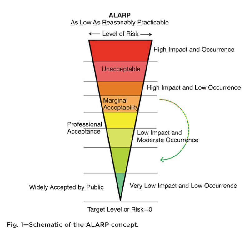
To work with risk requires an assessment of the impact and the probability of an undesirable outcome. For this reason, the actual expression of risk must be made on the basis of a quantitative risk assessment and may be compared to other industries where significant risk is an issue. The concept of “as low as reasonably practicable” (ALARP) is widely accepted in risk-based industries and by the public (Fig. 1).
For a thorough discussion of other well-construction-failure concepts, such as barrier effectiveness and age vs. era of construction, and the results of existing well-failure studies, please see the complete paper, which also contains a discussion of cementing issues and sources of naturally occurring gas and oil pollution.
Sustained Casing Pressure (SCP). One of the first signs of a compromised barrier is SCP, described as development of a sustained pressure between the tubing and casing or between a pair of casing strings that is not caused solely by heating of the well when placed on production. A sustained pressure may be bled off quickly but returns over hours or days after the annulus is shut in. Each of the annular spaces is a separate pressure vessel, and the casing strings are nested to give redundant barriers. Although one barrier may develop a leak, secondary barriers will contain the pressure and prevent a leak to the outside.
The presence of sustained pressure in the annulus area indicates that there may be a seepage-rate flow through at least one tubing string or casing string or through the cement; it also indicates that the pipe and cement on the outside of the annulus are containing the pressure (and fluids) and that there may be no significant leak to the environment outside of the well.
Why Well-Integrity Failures Produce Few Pollution Incidents
As opposed to loss of control during drilling in high-pressure reservoirs, such as occurred on the Macondo well, actual losses from completed and producing wells are very low for several reasons.
- Many drilling failures are the result of unexpected high pressure or other drilling-related factors where the pressure barriers are mostly dynamic (mud-weight and blowout-preventer control) and before the full range of permanent barriers is installed that exists in a completed well. The expected frequency of surface releases in production wells (completed wells) is between one and two orders of magnitude lower during production than during drilling. Workovers during the life of the producing wells do raise the risk of a release, although the frequency is still approximately one order of magnitude lower than it is during drilling activities.
- Completed wells are constructed of multiple barriers that have been tested and are monitored where applicable.
- Most importantly, the pressure inside a completed producing oil or gas well drops constantly during primary production, sharply decreasing the potential from fluids inside the well to flow to the outside of the well, considering the outside fluid gradients that increase outside (leak-opposing) pressure with increasing depth.
Groundwater Variation
Groundwater, brine zones, and produced water from oil and gas operations in a specific area do not have a constant composition. According to groundwater experts, overdrawing or overdrafting a ground-water reservoir (withdrawing water faster than it can be recharged) can produce notable changes in the reservoir-water composition, including pulling in contaminants from above and salt from below. This variance makes single-point comparisons of water quality practically worthless. Many fresh groundwater reservoirs are laterally or vertically connected to more-saline water sources. Salinity within a single reservoir often varies with depth.
Sudden changes in pressure within a groundwater reservoir will also change the amount of free methane gas by causing gas breakout into the free-gas phase. The only way to assess changes in a groundwater source is to establish a trend range and include seasonal factors, withdrawal rates, and other variables. Investigations of stray natural-gas incidents in Pennsylvania, for instance, reveal that incidents of stray-gas migration were not caused by hydraulic fracturing of the Marcellus shale. The possibility of some gas-migration events being related to drilling cannot be dismissed, however, because air drilling, when practiced, may be a cause for temporary upsets in shallow-well color and odor, although the worst of these migrations appear to be in areas with known examples and a known history of shallow-gas flows that predate drilling.
Gas migration in the subsurface occurs principally by advective transport from areas of high pressure and is influenced by temporal changes in barometric pressure, soil/bedrock porosity and permeability, and precipitation that influences pore-water levels. Methane is the most common gas in groundwater. Shallow methane may be from sources both thermogenic (maturation of depositional organics in the reservoir) and biogenic (biological breakdown of organic materials carried into the reservoir). Free (nondissolved) methane gas exists in many water reservoirs under the caprock or in rock layers, and methane gas is frequently desorbed from organic formations such as coal or shale as the pressure is reduced by producing the water from these formations.
Bubbles Around a Wellhead
The presence of bubbles in well cellars or through soil around the wellhead may or may not be an indicator of leaks from the well. Any disturbance of soil by drilling, digging, pile driving, or even walking (e.g., through a swampy area) is frequently accompanied by release of methane gas, particularly where natural methane in the soil is more highly concentrated. This type of seepage is usually short-lived except in the presence of natural seeps fed by deeper reservoirs along an established seep path. Depending on the depth of disturbance, the bubbles may decrease or stop in seconds to days. Composition of this gas may be biogenic or thermogenic, because composition of natural-seep gas indicates that this gas is commonly from deeper reservoirs and is therefore overwhelmingly thermogenic.
This article, written by JPT Technology Editor Chris Carpenter, contains highlights of paper SPE 166142, “Environmental Risk Arising From Well-Construction Failure: Difference Between Barrier and Well Failure, and Estimates of Failure Frequency Across Common Well Types, Locations, and Well Age,” by George E. King, Apache, and Daniel E. King, WG Consulting, prepared for the 2013 SPE Annual Technical Conference and Exhibition, New Orleans, 30 September–2 October. The paper has been peer reviewed. Published: November 2013 SPE Production & Operations, page 323.