Replicating field conditions for flow assurance experiments at a reasonable cost often presents many challenges, particularly when it comes to designing an experiment with appropriately scaled geometry, an expert said.
At a presentation held by the SPE Flow Assurance Technical Section, Kevin Supak discussed various techniques the Southwest Research Institute (SwRI) implemented to perform gas hydrate tests under adequate flowing conditions. Supak is a senior research engineer in the multiphase flow and flow assurance section at SwRI.
Replicating field conditions in hydrate testing can be difficult for a variety of reasons. It typically requires a high-pressure gas source, and pipelines with larger diameters that researchers unaffiliated with an operator will likely not be able to access. Supak said operators may not be willing to participate in a field study because it might require plugging a producing asset. In addition, sensing techniques may also be limited for a field study because operators may not have the equipment needed to obtain the data required for a successful test, and running a small-scale laboratory test may prove problematic when trying to glean useful information for in-field operations.
“You’re usually limited to an existing facility that’s there,” Supak said. “You may have pressure. You may have temperature. That’s not a lot of information to be able to help you locate a hydrate plug or mitigate one. So then you turn to laboratory and flow loop tests, but how do you scale a test like this? What diameter [pipeline] do you need to answer for the kind of flow regime you need to match? How much length do you need to make sure to get the proper heat transfer?”
Supak identified three general testing methods that researchers typically use to examine hydrate behavior. Autoclave, or static, tests are small-volume tests that focus primarily on inhibitor performance. Bench-top, or lab-scale, tests involve the formation of hydrates at high temperatures and the study of the deposition processes that take place at those higher temperatures. Field-scale tests are typically run in smaller pipe sections (between 2 to 4 in. in diameter) but are scalable to field conditions, and generally involve the use of realistic fluids one would encounter in the field, such as natural gas, water, and oil.
Supak’s presentation focused on successful field-scale tests, like one SwRI ran on hydrate blockages in a test pipeline in Wyoming. The pipeline was 900-psi, 4 in. in diameter, and slightly more than 3 miles long. The system had between 10% and 20% water cut, and the researchers used methanol to mitigate hydrate risks. The velocity in the pipeline was approximately 7 ft/sec and it yielded stratified and slug flow in the system.
SwRI installed instruments for the test by excavating the ground in five locations, creating “bellholes” that were then heated to prevent plug formation in those specific areas. Bellhole 4 was equipped with dual gamma densitometers that estimated hydrate plug length as it passed through the pipe and plug velocity after depressurization.
The test showed that, with computational simulation and knowledge of its location, a plug could be dissociated safely using single-sided depressurization, and that highly permeable plugs are likely to dissociate faster, thus lowering the risk of blockage. However, Supak said the tests also demonstrated the need to understand the formation and deposition process so that researchers could better replicate field conditions. He said the fragility of hydrate plugs was a particular concern: When they begin forming, plugs can be easily sheared as they travel through a pump or a compressor, making it more difficult to develop an accurate field setting.
“We want to be able to control [formation and deposition] more discreetly,” he said. “That way, we can understand how the plugs even got there in the first place. Again, we ask ourselves questions: How do you scale geometry for a system like this? How much pipe is really needed to be able to get a heat transfer? What kind of diameter do we want for this kind of system? The most important question is how do you produce and transport these fragile solids?”
To answer these questions, SwRI launched an internal research project to further study hydrate formation, agglomeration, and deposition. The primary goal of the project was to design a system capable of pumping hydrate slurry and free gas without shearing particles in the system. Supak said another goal for the project was to develop methods and instrumentation for quantifying deposition as well as the bulk slurry present in the flow.
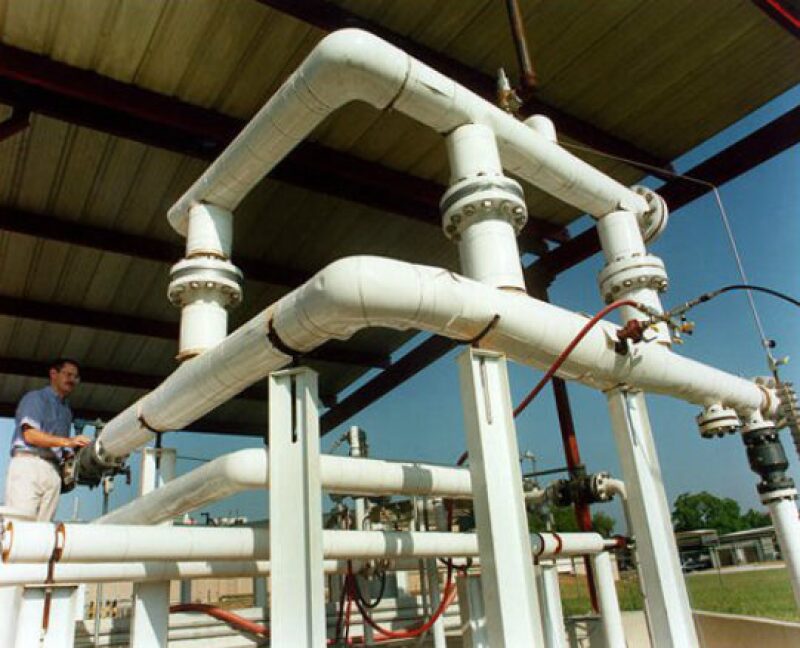
The flow loop worked by flowing natural gas and water through a test loop section. It contained an inclined section of jacketed pipe that controlled temperature. The flow traveled through the inclined section, a horizontal section, and a declined section. The gas was separated from the flow at the exit of the jacketed pipe, recompressed, and reinjected downhole. Supak said this process caused a differential pressure in the flow loop system that was similar to gas lift, thus allowing the fluids to move through the test section without shearing the hydrate particles.
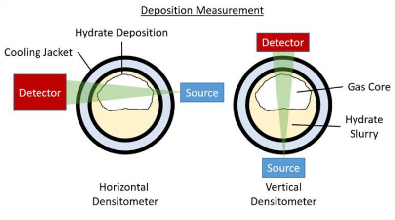
SwRI used two gamma densitometers to measure hydrate deposition within the flow loop. A horizontal densitometer was mounted off the center access in order to adequately monitor the deposition occurring on the upper pipe wall, and a vertical densitometer monitored liquid holdup in the system as the hydrate layer slurry levels fluctuated. The densitometers helped them measure a maximum deposition of approximately 1 in., a figure Supak said was significant for a 3-in. pipeline.