
While subsea processing is not a new concept, recent project economics have led to more applications, ranging from single-phase or multiphase boosting and subsea separation and boosting to future gas compression projects. Subsea equipment suppliers are working to establish technologies that can meet the unique challenges of subsea processing, and operators are trying to capitalize on these technologies by qualifying them in a timely fashion that satisfies the overall project schedule. Certain technologies, such as subsea compact separation, are considered enabling technologies for subsea processing, especially in ultradeepwater applications.ExxonMobil Upstream Research Company recently completed a technology development and qualification program, which included performance tests on an integrated subsea compact separation system for ultradeepwater applications.
Because of extremely high internal and external pressures, unconventional separator designs must be used in ultradeepwater applications. A key challenge is the design of separators that can achieve acceptable gas/liquid and oil/water separation performance while still meeting module size and weight restrictions. To position itself for future ultradeepwater applications, ExxonMobil developed a subsea compact separation system concept using proprietary and vendor-supplied technologies (Fig. 1).
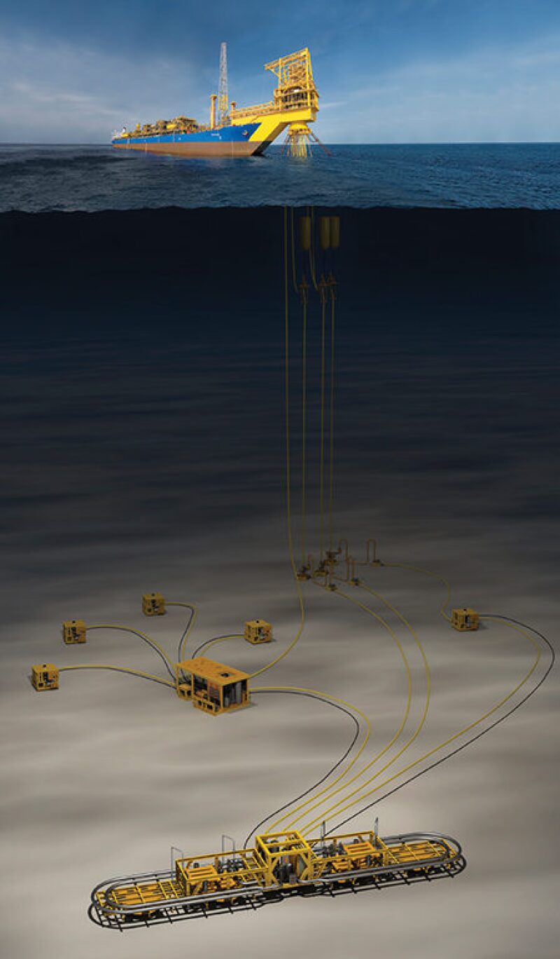
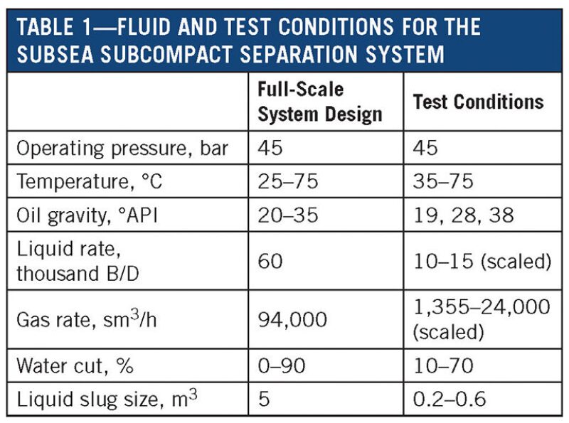
The subsea compact separation system is designed for a water depth of 3000 m and internal design pressures up to 690 bar. It is flexible, robust, and scalable to particular applications. Each separation train has a capacity of 60,000 B/D, and it can handle a wide range of operating conditions with oil gravity ranging from 19 °API to 38 °API, water cuts from 0% to 90%, varying gas/oil ratios, and liquid slugs of <5 m3. Although larger slug sizes and different oil gravities can be accommodated, the separation equipment used during the qualification tests was scaled for these conditions.
Historically, the qualification of subsea separators has been project-specific, often dictating the timeline of the project with key decisions being dependent upon the outcome of the qualification. ExxonMobil has taken a global approach in developing and qualifying subsea processing technologies. It has qualified a number of subsea technologies covering a wide range of operating conditions and fluid properties that encompass its subsea portfolio. This approach reduces the cost of qualification and will streamline schedules for future subsea projects. Performance tests on the compact separation system, which used all the individual components, were recently completed at ProLabNL in Arnhem, The Netherlands, under realistic operating conditions with methane, crude oil, and simulated produced water.
Components of Separation System
A schematic diagram of the integrated system tested at ProLabNL is shown in Fig. 2. It consisted of the following compact separation components:
Slug generator. This unit is a specially designed device that releases set volumes of liquid slugs into the system. The unit was bypassed for the majority of the tests, except during slugging trials.
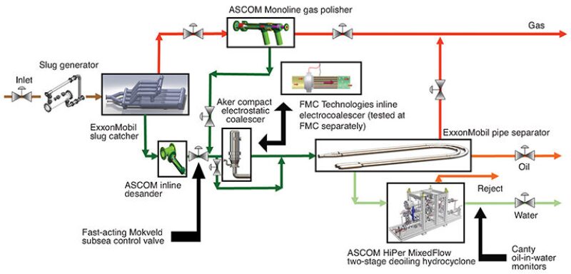
Slug catcher. The slug catcher (as shown on the title page) reduces transient flows to downstream equipment and provides bulk gas/liquid separation. This “finger-type” slug catcher, which was developed by the company for a liquid-dominated inlet, is capable of handling relatively smaller liquid slug sizes when compared with slug catchers typically used onshore that receive gas from offshore fields. In a subsea installation, the slugs are not expected to be very large, as the separation skid is placed near the wellheads. This resulted in a relatively compact finger-type slug catcher design. Although there is no sand in the fluids tested at ProLabNL’s high-pressure flow loop, the slug catcher is equipped with sand-jetting headers to help fluidize any sand that may accumulate in the liquid headers and move it downstream with the liquid outlet.
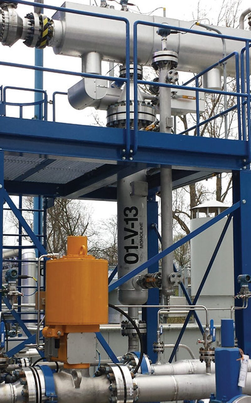
ASCOM Monoline gas polisher. This unit is a compact inline cyclonic device that removes liquids from the gas stream leaving the slug catcher (Fig. 3). Any liquid carryover from the slug catcher resulting from droplet entrainment or foaming will be removed in this device and collected in a liquid boot. This liquid is then reintroduced back into the liquid line downstream of the desander.
Inline desander. The liquid from the slug catcher passes through an inline desander to remove up to 95% of the produced sand. The sand removal performance of the inline desander was previously verified in the low-pressure, model fluid flow loop at ProLabNL. In the high-pressure flow loop, the inline desander is installed to account for the additional pressure drop and any effects on the oil/water separation due to shearing.
Fast-acting control valve. In the integrated system, the valve controls the liquid level in the slug catcher and adds additional pressure drop so that the liquid exiting the Monoline can drain back into the liquid line.
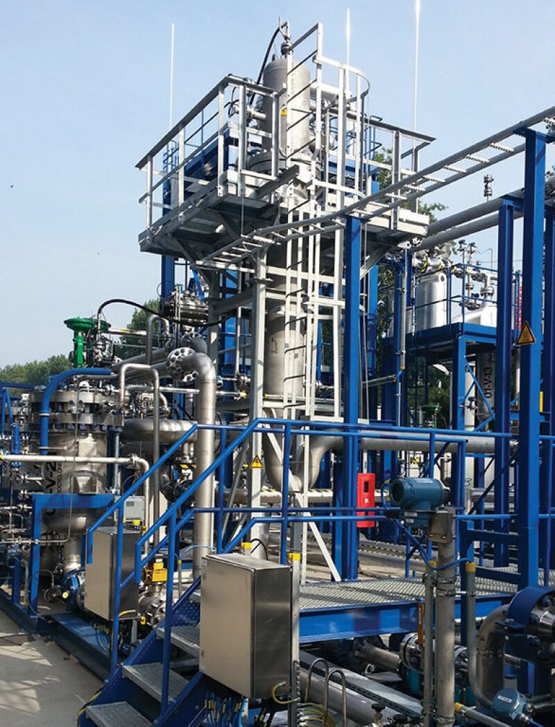
Aker compact electrostatic coalescer (CEC). In certain applications, an electrocoalescer could be used to enhance the oil/water separation (Fig. 4). Electrostatic coalescence will be required to increase overall capacity and improve oil/water qualities in medium to heavy crude oils at low temperatures. The electrocoalescer was tested at ProLabNL as part of the compact separation system with heavy oil. Any flash gas generated through the control valve or carried under from the slug catcher has an opportunity to be removed at the top of the CEC. ExxonMobil also performed a technical feasibility test on the FMC inline electrocoalescer, which is not yet commercially available, at FMC’s facility with the same crude oil blends and temperatures with promising results.
Pipe separator. The oil/water mixture leaving the CEC immediately flows into a proprietary pipe separator, which was developed by ExxonMobil, and is separated. Level control of the interface is crucial to minimize emulsion carryunder in the water outlet. A nucleonic level detector is installed in the pipe separator to detect the oil/water interface level. As with most separation units, one phase is sacrificed over the other. For this system, a clean water phase is controlling the interface level, as the separated water is reinjected into a disposal well. Depending on tieback distance and water depth, higher water-in-oil (WIO) concentrations could be tolerated. For this qualification, up to 10% WIO was acceptable.
Deoiling system. To assist with water polishing, a two-stage ASCOM HiPer MixedFlow deoiling hydrocyclone skid is located downstream of the pipe separator’s water outlet. It consists of two vessels: one containing 3-in. bulk hydrocyclone liners and the other containing 2-in. polishing hydrocyclone liners. The skid could be bypassed if the water flow rate was too low. The reject streams were combined and reintroduced into the oil outlet from the pipe separator.
After the separation test skid, the fluids are recombined in a very large three-phase plate pack separator at the ProLabNL facility. The individual fluids are pumped, and flows are controlled and remixed in the line upstream of the test skid. A shear valve is included to test the effects of additional pressure drop on the system.
All the tested components, including the flow loop itself, were built from duplex stainless steel material. This prevented corrosion of the flow loop and provided better control of the water quality. With carbon steel, the water quality would have become a problem because of corrosion particles affecting the test results over time.
Fluid and Test Conditions
The crude oils came directly from the production facilities with trace amounts of chemicals for corrosion and emulsion control. No additional chemicals were added during the tests.
Table 1 shows the conditions used for testing of the system. A decision was made to test the system with methane gas instead of nitrogen. Methane diffusivity into heavy crude oils is approximately four times higher under the given operating conditions, which affects the crude oil’s density, viscosity, and interfacial tension. Tests with nitrogen at this pressure would not have provided the representative data needed to predict performance and scaleup effects.
Performance Results
The system was tested for about 9 months under various conditions. Approximately 600 points were tested, in which 24 samples were collected for each test point. With this performance data, the overall system performance can be predicted, with confidence, and the individual components can be qualified. Below is a summary of the test results.
Slug catcher. Minimal liquid carryover was observed in the majority of the test points. As can be expected, the gas outlet quality improved at lower liquid levels to the detriment of higher gas carryunder in the liquid. Determining the optimum liquid level to minimize liquid carryover and gas carryunder was initially a challenge.
Fig. 5a shows that as the liquid level in the slug catcher decreases, the gas carryunder in the liquid improves for this slug catcher design until a minimum liquid level is reached, at which point the higher liquid velocity in the liquid headers starts to entrain gas bubbles into the liquid outlet. Although it may seem counterintuitive, higher liquid levels harm the liquid quality. At very high liquid level, insufficient gas space causes the liquid flow regime to transition into plug flow, instead of stratified flow, causing more turbulence inside the liquid headers.
As shown in Fig. 5b, the liquid carryover increases significantly for a relatively small change in liquid level. This is because of the insufficient gas space for this given gas rate, which induces wave formation and re-entrainment from the liquid surface.

|

|
ASCOM Monoline gas polisher. Previous tests at Southwest Research Institute (SwRI) at very high pressures (from 100 bar to 180 bar) showed that the liquid removal efficiency improved dramatically at higher liquid loadings, above 2% liquid volume fraction (LVF) up to about 15% to 16%. A similar trend is observed in the data from the tests at ProLabNL. Fig. 6 shows that the liquid removal efficiency decreases when the LVF is very low at approximately 1.7%. Above this value, the liquid removal efficiency was very high at nearly 100% for most of the test conditions, particularly with the higher gas rates for which the unit was designed.

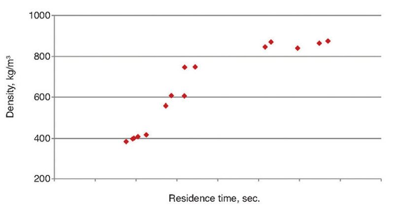
Gas carryunder from the gas polisher vertical boot, as shown in Fig. 7a, was observed when the liquid residence was low, either due to higher liquid carryover rates or low liquid level in the boot. The minimum residence time for this particular crude oil can be seen from the step change in the liquid density measurement leaving the boot, an indication of gas carryunder (Fig. 7b).

|
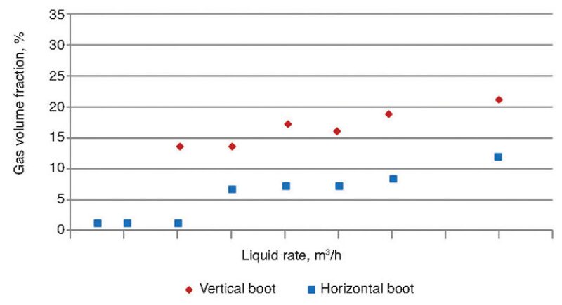
Since this liquid is reintroduced into the liquid line from the slug catcher, gas carryunder should be minimized from both the slug catcher and the gas polisher’s liquid boot. Gas carryunder from the two devices directly affects the oil/water separation in the downstream pipe separator. To improve degassing performance in the liquid boot, a horizontal boot orientation was investigated in ProLabNL’s low-pressure, model fluid flow loop.
Vertical and horizontal boot orientations were tested with model oil and air under the same test conditions. For comparison, the liquid residence time was the same for both configurations.
The degassing performance for the boot orientations is shown in Fig. 8. The horizontal boot outperforms the vertical boot in the measured gas volume fraction (GVF) in the liquid outlet, because the horizontal boot provides more liquid surface area and a smaller distance for the bubbles to travel to the surface compared with the vertical boot orientation.
The horizontal boot does have drawbacks in that it is difficult to control the liquid level, because it requires a fast-response level instrument due to its limited span length. Further, it is more sensitive to installation effects, as tilt could potentially cause an unsealed liquid outlet.
The horizontal boot configuration was not tested in the high-pressure flow loop.
Pipe Separator. The pipe separator performed better than expected, but the performance was dependent upon the oil/water interface level. Small changes in the interface level led to significant changes in the measured oil-in-water (OIW), as the emulsion layer could be entrained in the water outlet at lower interface levels.
The oil/water qualities improved at higher temperatures because of lower viscosity and less stable emulsion. Lower flow rates and higher water cuts also improved performance, similar to more conventional separator designs. The oil/water separation improved with the additional length of the pipe separator; however, it was not a linear relationship. The length versus performance improvement can be optimized for lower viscosity fluids and higher water cuts.
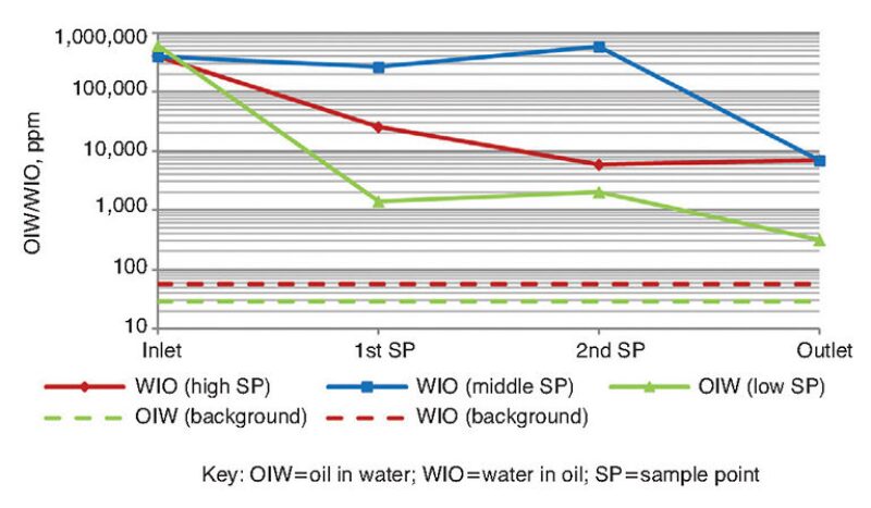
Fig. 9 shows the pipe separator oil/water separation performance as a function of length. This particular test condition is difficult because of the low temperature of the fluid and the midrange water cut. The emulsion becomes more stable and more viscous as it approaches the phase inversion point.
As this is a flow loop, the separation from the flow loop’s plate pack separator is imperfect. In this case, the OIW leaving the flow loop’s plate pack separator was about 100 ppm, as shown by the green dashed line in Fig. 9. The WIO background value was higher at approximately 4,500 ppm.
Fig. 10 shows that increasing the operating temperature improves the performance, as indicated by the oil and water qualities. Note that the OIW and WIO background values leaving the flow loop’s plate pack separator also decreased. Figs. 9 and 10 provide a small example of the data collected over a much larger range of conditions.
Conclusions
ExxonMobil’s subsea compact separation system proved to be robust over a wide range of test conditions. As expected, the performance and capacity decreased with heavy oil without electrostatic coalescence. Although not shown in this article, electrostatic coalescence improved the performance significantly.
Also not presented was the ability of the slug catcher to capture and hold the liquid slugs while minimizing the effect on the downstream equipment. Control parameters were changed for the slug catcher to hold the liquid slug longer, gradually releasing it into the downstream equipment. In this integrated design, the control system is important and needs to be evaluated by a dynamic simulation; however, the dynamic model of a once-through, real system could not be validated in a closed-loop system because of pressure balance constraints.
The cost of developing and applying a subsea separation system is significant; therefore, it can be uneconomical if the system is unable to provide a sufficient increase in production rates, or if reliability issues—such as sand management—cannot be mitigated.
The design of a subsea processing system is a balance between the mechanical design aspects given the module size and weight constraints and the production rate required for project economics. By understanding, with confidence, the performance and overall capacity of a compact separation system, the technical risks can be minimized, and a project could become more attractive and successful.
With this qualification effort, ExxonMobil has added another set of technologies to its arsenal for deepwater developments that can be easily customized for a wide range of field conditions.

| Ed Grave is the fractionation and separation adviser at ExxonMobil Upstream Research Company and the vice chairman of the SPE Separations Technology Technical Section. He may be reached at edward.j.grave@exxonmobil.com. |

| Michael Olson is a senior research engineer at ExxonMobil Upstream Research Company. He may be reached at michael.d.olson@exxonmobil.com. |