As a followup to the SPE webinar in November by Joao Paulo Sena on separation internals, Field Installation and Inspection To Enable the Potential for Good Performance, this article provides some additional lessons learned on the selection/design and installation of internals. Good off-/on-site planning will minimize the separator turnaround.—R.W. Chin, Savvy Separator series editor
Retrofitting separators with internals can be considered to be a five-step process.
- Definition of data, properties, flow rate ranges, design margin, performance specifications, and baseline current performance.
- Process selection and design of internals. What are you trying to accomplish, e.g., improve flow distribution, reduce droplet shearing, increase gas capacity?
- Supports. How to support the internals? Use existing supports? Weld to vessel shell? Alternative supports such as expansion rings? Will vessel in its current condition support new internals?
- Installation. How to prepare site/vessel (e.g., isolation, cleanout) and actually install the internals and supports once they are fabricated.
- Verification/acceptance. How to verify the requirements are met. For example, measure carry-over, or monitor compressor vibration levels. The baseline data from Step 1 is thus very useful.
Previous articles in the Savvy Separator series have covered steps 1, 2, and 5 in some fashion. This article provides some additional lessons learned on the supports and installation steps, Steps 3 and 4 above.
Support Selection and Design
- As-built drawings
- Flexibility of installation for out-of-round vessels
- Isolation for galvanic corrosion
- Gasket material and type selection
- Lifting weights and mechanical calculations (including pressure differentials)
The starting point for designing the supports for the retrofit internals is the as-built drawings. It is key to keep vessel drawings up to date, especially if field modifications have been made. Talk to field personnel to check their records (and memory). What the field has in their office may be different than what you have in your office.
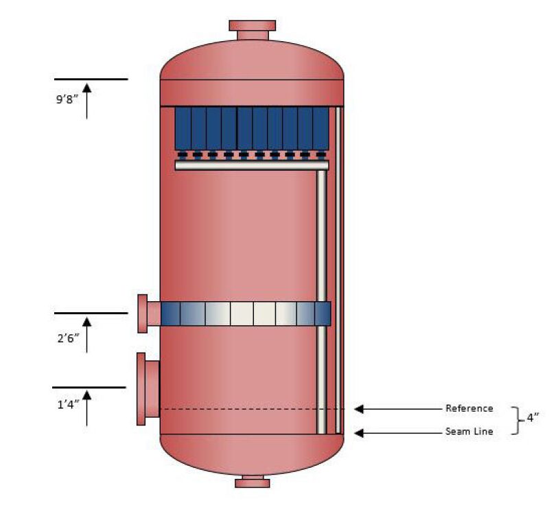
Check with the vessel and internals supplier as well. Do you have the most recent vessel inspection report? One item to be aware of is the reference line for elevations (vertical or horizontal). The vessel drawing should have a clearly marked reference line from which all distances are measured. This line is typically 2–6 in. from a seam line or a tangent line, depending on design pressure (Fig. 1).
Internals can be supported in many ways, e.g., use existing supports, expansion rings, welding new ones to vessel if allowed. Supports should be designed with some flexibility because the vessel is not perfectly round. ASME Boiler and Pressure Vessel Code Section VIII permits an ovality, (Dmax-Dmin)/D, limit of 1% (no opening nearby) where Dmax is the maximum measured diameter, Dmin is the minimum measured diameter, and D is the nominal diameter of the vessel.
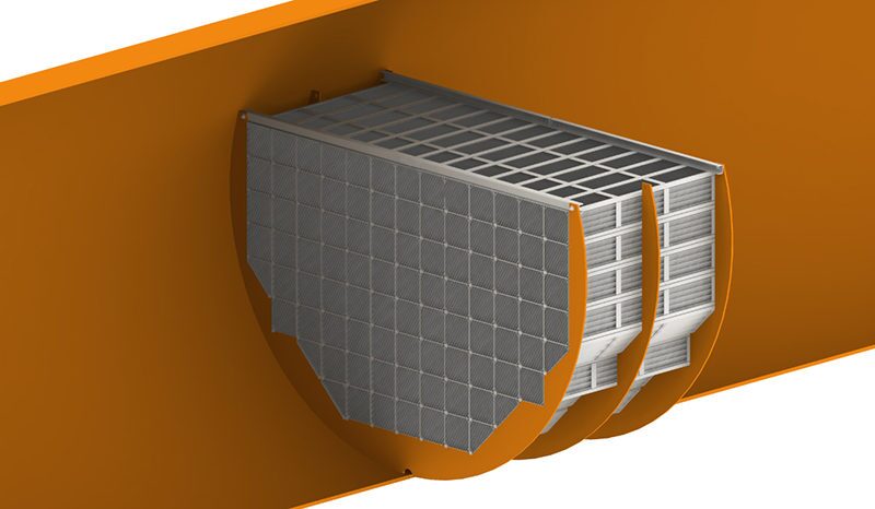
This ovality sometimes comes into play when you need to support square or rectangular internals. Fig. 2 shows a plate pack installation. Slightly larger or slotted bolt holes can be used. Smaller sections can more easily adapt to the shape of the wall.
Internals are typically made from stainless steel (e.g., 316) while the vessel is carbon steel. For galvanic corrosion to occur, you need an electrolyte connecting the different metals, so this is typically applicable to water-wetted surfaces. Gaskets and bolt isolation kits are typically used to isolate the internals from the vessel to mitigate galvanic corrosion, especially in freewater knockouts. Make sure you use gasket material suited for your service. Typical materials are PTFE (polytetrafluoroethylene) and Viton (a synthetic rubber and fluoropolymer elastomer). Be aware of explosive decompression.
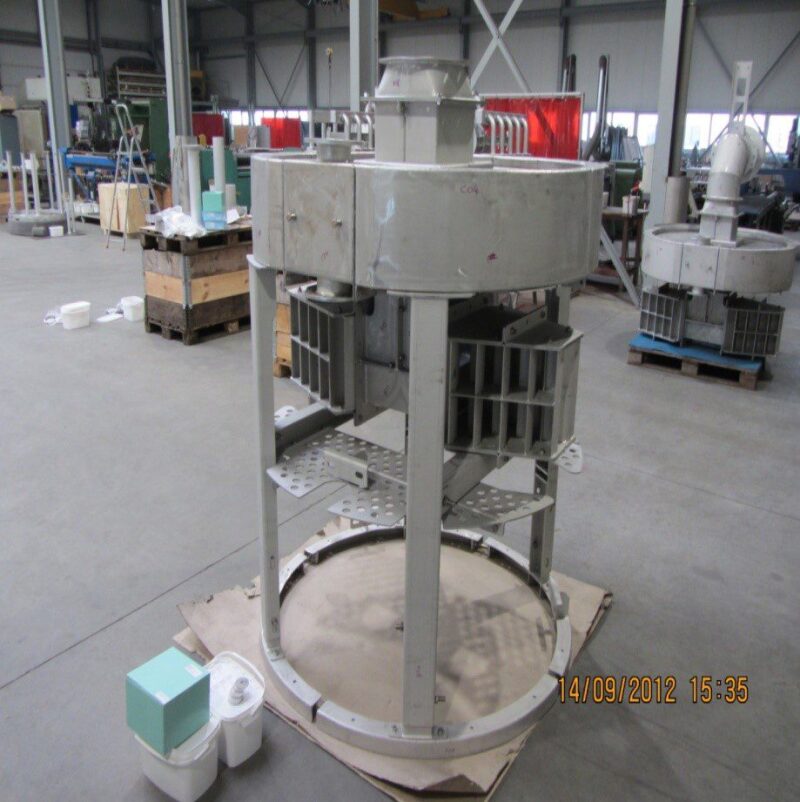
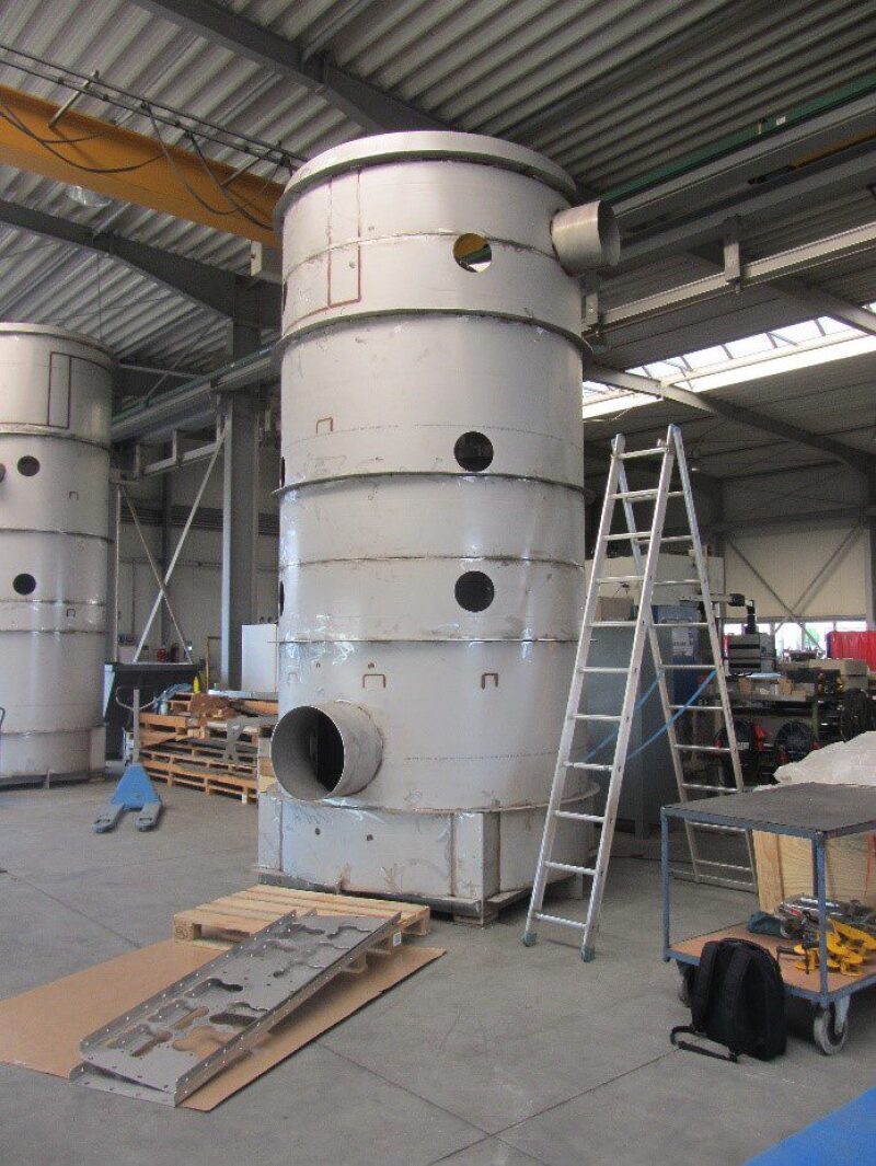
The weight of individual parts (Fig. 3) of the internals should also be addressed in the design phase. The National Institute for Occupational Safety and Health provides guidelines that depends on multiple factors such as lifting height and body twist. The maximum weight is 51 lb, which is then adjusted for the different factors. The equation does not cover, however, lifting in a confined space. Individual companies may also have their own recommended limits.
The internals design should account for mechanical forces such as due to slugging and pressure differentials (creating an uplift force) across a device. Mechanical calculations must be made to confirm that supports (and the vessel) can take the weight and forces acting on the new internals as well.
Offsite Planning
- Fabrication shop assembly/vessel mockup/practice assembly
- Removal and installation procedures
- Sparing for new (and old) internals (especially gaskets, nuts, bolts)
The fabricated internals are typically inspected by the purchaser or their third-party representative. Ensure all parts are marked/numbered including top/bottom or right/left as necessary. In addition to the individual components, an inspection of the complete assembly of the internals is required to ensure proper fit.
A step-by-step procedure for the actual removal and installation part of the job needs to be developed cooperatively between vendor, owner/operator, and other relevant service providers. The job duration time needs to be estimated.
Although the actual vessel is not available for trial fit, dimensions on the interface with the vessel supports should be verified and checked. For space-constrained vessels or complex installations, a vessel mockup is recommended so that the installation team can practice assembly that conforms to on-site limitations (Fig. 4). Problems with tightening nuts and bolts and other problems can then be identified. Understand which tools will be required to install the internals (Fig. 5).

|

|
Fig. 5—Understand how the internals are installed and the required tools. Credit: TechnipFMC.
Sparing should not be overlooked. Make sure you have extra nuts, bolts, and gasket material. It is not uncommon to strip stainless steel bolts. Ten-percent extra is a common amount, but more may be necessary if the material is not that readily available. And as mentioned above, not all vessels are circular so an extra strip of gasket material may be required to provide better sealing of the internals against the vessel or other supports.
On-Site Installation Planning
- Check equipment list on delivery
- Safety: vessel/site preparation, isolation, ventilation, air-quality check, manway watch, confined space
- Lift plans, internal scaffolding, coating protection
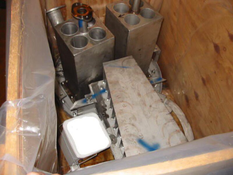
Check the delivered equipment against the packing list as well as for damage (Fig. 6). And check again when the equipment is delivered to the vessel site. It is not unprecedented that a piece is missed during repacking, either from the fabrication shop or from an onshore delivery point. Although a practice assembly may have been conducted off-site, consider one on-site by the actual installers for complicated internals. Have the vendor’s technician on-site to help if the vendor is not doing the installation.
When planning the installation, safety should be No. 1 one on the list. Early in the job planning, there will be a hazard identification/review. On-site planning will include job risk assessments in addition to procedures. Not a comprehensive list, but emptying the vessel, vessel isolation, pressure release, ventilation, air-quality check, confined-space entry, vessel cleaning (including decontamination, waste-handling/disposal), and vessel inspection/contingency repair plans should all have approved procedures. Confined-space entry may call for positive isolation. Isolation of multiple vessels or even a facility shutdown may be needed.
Lift plans may be required to move necessary equipment on and around the site, for vessel preparation, or for installation of internals inside a vessel. Especially in vertical vessels, scaffolding is required for the retrofit. Follow fall protection requirements. Care must be taken to protect any internal coating with mats. Cover bottom nozzles, or plug them with rags. Bolts and nuts will inevitably fall and if they fall into a drain or instrumentation nozzle, it will be a problem.
Installation
- Removal of old internals, inspection/re-gasketing of reused internals
- Check as-builts of supports (prior to any cutting), update as-builts if field modifications
- Layout internals and follow vendor installation steps
- Inspection
Take pictures (if possible) of vessel and internals upon entry, and again after cleaning, prior to any modifications. Inspection of the vessel may dictate repairs.
Follow the existing equipment vendor’s procedures for removal, which may be different than the new supplier. Inspect any equipment that is to be reused and provide new gaskets. Once the existing internals have been removed and before cutting any supports, check the as-built drawings against what you actually have in the vessel. Then check with the internals supplier to see if any difference can be accommodated with the delivered internals and supports. Guidelines were given in a previous Savvy Separator article if supports need to be welded to the vessel shell.
Lay out the equipment in the staging area. This staging step, depending on timing and space, could be part of the on-site preparation prior to removing the existing internals. Follow the supplier’s installation steps. Some parts must be installed prior to others to have enough room to tighten bolts for example. The individual pieces are typically marked/numbered.
Inspection of the installation should follow vendor procedures. Note that some inspection is required after a given installation step, depending upon access. An inspection checklist may include:
- All internals installed as per drawing and/or installation manual
- All bolts installed with double nuts secured
- All sealing/interconnecting gaskets installed and leak-checked
- Isolation kits installed between dissimilar metals where required
- Digital photographs of internals/supports taken from various viewing angles
Post-Installation (Before Buttoning Up Vessel)
- Internal coating, check for potential damage and repair
- Check for mats, tools, gloves, etc. before closing up vessel
- Update the as-builts
- Follow procedures for vessel cleaning and startup
After the installation is completed/inspected and scaffolding removed, check the coating and repair any damage. Patching and curing of the coating can affect the shutdown time. Remove mats, tools, loose nuts, bolts, etc. There have been reports of vessels not draining because of a mat left in the vessel or downstream pipe strainers plugged by bolts. Especially check any drains on the bottom of the vessel for loose parts. Update the as-builts if needed. Follow procedures for startup.

Robert Chin is a cofounder and past chair of the SPE Separations Technology Section, past chair of the SPE Gulf Coast Section’s Projects, Facilities, and Construction (PFC) study group, a member of the SPE Annual Technical Conference and Exhibition’s PFC paper selection committees, and the author of Chapter 3, “Oil and Gas Separators,” in the SPE Petroleum Engineering Handbook, Volume III, Facilities and Construction Engineering. Chin is a consultant and cofounder of Padden Engineering. He retired from Shell in 2014. He joined the company in 1981 and conducted advanced research on multiphase flow, leak detection, and separations. In 1999, he left the company to form a separator design and supply company. He returned to Shell in 2006 and led teams in facilities for enhanced oil recovery and subsea processing research and development. Chin holds a degree in applied mathematics and a PhD in fluid mechanics from Harvard University. He may be reached at r.w.chin@sbcglobal.net.

Peggy Lane is BP’s senior process engineer, separation and sand. She is responsible for gravity separation and surface sand handling expertise for upstream, and also has an extensive background in produced water handling and waterflooding. Lane has 28 years of process and production experience in design and operations roles in the US, UK, and Middle East. She holds a BS in chemical engineering from California State Polytechnic University, Pomona. She can be reached at peggy.lane@bp.com.

Victor van Asperen has several years of experience in separation, including the process design of more than 150 separator projects. He has worked at FMC Technologies Separation Systems (formerly CDS Engineering) for the past 16 years in different geographical areas: The Netherlands, United Arab Emirates, and the US. He has worked in research and development, computational fluid dynamics (CFD), process engineering, and sales and management. Van Asperen holds an MSc in chemical and biochemical engineering and a professional doctor of engineering degree in process and systems design from the Delft University of Technology.