An underperforming scrubber that was suffering from too much oil carry-over is described and the consequences of this carry-over for the processing system are explained. A brief analysis of the scrubber design is presented and the potential causes for the underperformance are listed. Several options for resolving the problem are discussed, and the selected option is summarized along with a comparison of the separation performance data obtained before and after the modification.
Introduction
In Part 2 of the series published in the August issue of Oil and Gas Facilities, the effect of inlet geometry on separation performance was discussed using several real-world examples. One of the examples was a vertical gas scrubber that was installed to protect a glycol dehydration system from crude oil carried over from a production separator. The separation performance of the scrubber was unsatisfactory, and the problems caused by the crude oil contamination of the glycol system were significant enough to warrant improvement. In addition, further loss of performance at future higher rates of gas/liquid inflow was also a concern.
Original Scrubber Design
Fig. 1 is a schematic of a two-stage scrubber used upstream of compressors and dehydration systems. The first stage is the inlet region, where bulk gravity-driven gas/liquid separation occurs, and the second stage is the mist extractor for small drop removal. In this case, gas from an upstream production separator is split into two trains, each consisting of a scrubber, gas compressor/cooler (GC), and filter separator. The gas from the two trains then combines before flowing into a glycol dehydration system.
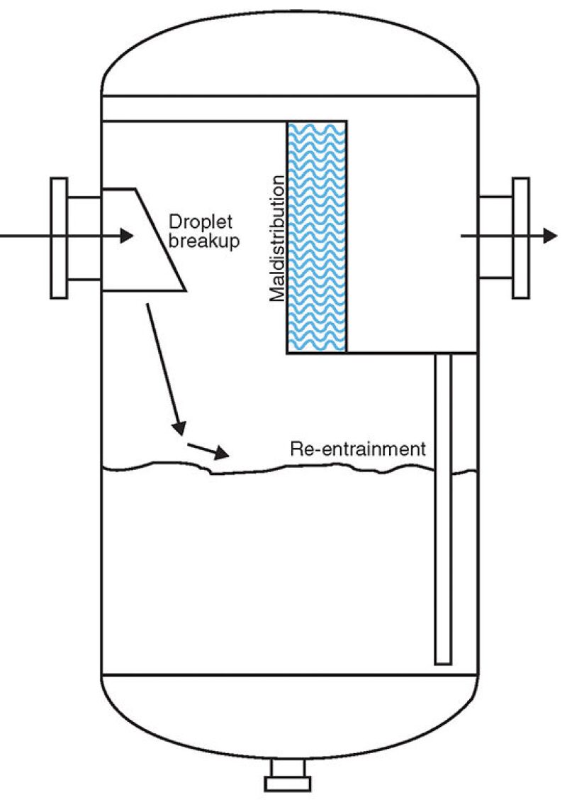
The inlet and outlet nozzles are installed on the shell diametrically opposite each other. A mist extractor is placed in between the two nozzles. To prevent direct impacting of the flow on the mist extractor, the inlet is baffled, directing the flow downward.
As noted by Chin (2015), several problems may occur:
- Small(er) drops and foam created by the fluid impact on the baffle
- Liquid re-entrained from the liquid surface due to the high velocities of gas impacting the surface of the liquid
- Foam and gas entrainment into the liquid caused by jetting into the liquid surface
- Poor flow distribution over the mist extractor caused by the reversing and swirling flow
Signs of poor scrubber separation performance were:
- Continuous level of liquid carry-over that overwhelmed the filter separator, resulting in contamination of the downstream glycol dehydration system with approximately 20 US gal/D crude oil
- Inability of the scrubber to handle high liquid loads during an upset (surge in gas rate and liquid) in the upstream separator, resulting in significant glycol contamination in a short period of time, in the order of 100 US gal of crude oil
Debottlenecking Options
Options that may be considered to better protect a glycol system are installation of a new inlet separator upstream of the scrubber, replacement of the existing scrubber with a more efficient or larger one, the addition of another scrubber (e.g., inline or other) up- or downstream of the existing scrubber, and the modification of internals.
Considerations when selecting an option should include the effectiveness of the design, the downtime resulting from the installation, the available space, added complexity, delivery time for the equipment, the cost of the total installation, and safety.
In the present case, modifying the internals was deemed the best option mainly because of the lack of space for an external scrubber (and the complexity added to operations).
Modified Scrubber Design
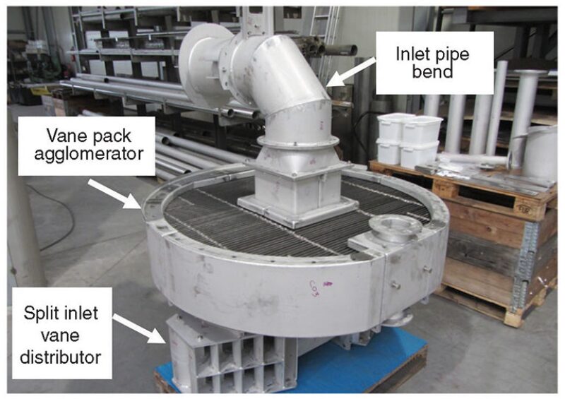
Fig. 2 is a schematic of the modified design. The new internals include a split inlet vane distributor, anti-re-entrainment plates to protect the liquid surface from the impact of the gas flow, a vane pack agglomerator, and demisting cyclones.
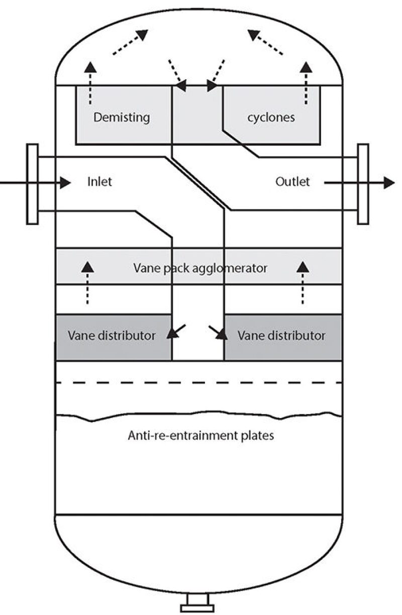
The intention was to revamp the scrubber into a more efficient design with an inlet flow below the demisting device(s). This would allow for an improved two-stage separation with bulk separation of the large liquid drops followed by removal of the smaller drops. One might even consider this to be a three-stage separator with the addition of the vane agglomerator.
Because the inlet and outlet nozzles were located at the same elevation in the original design, piping had to be installed inside the vessel that extended through some of the internals to implement the new design. These new extensions of internal pipes decrease the flow area available for gas and liquid, thus increasing their velocities. This needed to be accounted for in the design/rating of the new internals.
Pipe bends were installed to lead the flow downward before dividing into two vane-type inlet spreaders (Fig. 2). The vane spreaders reduce the velocity by at least fourfold, allowing large drops to fall out. Due to the proximity of the vane inlet to the liquid surface and the high inlet velocities, anti-re-entrainment plates were placed over the liquid surface.
Even though the velocities are greatly reduced, the gas exiting the inlet vane distributor is directed at the vessel wall and partially deflected downward across the liquid surface, potentially leading to re-entrainment. The gas then flows upward through a vane pack, which removes large drops and agglomerates smaller ones. Mesh was not used due to plugging concerns, but it would also not have been the best choice considering the high gas-load factor. The small drops are then removed by the demisting cyclones. Pipe bends lead the gas flow back down from the vessel head and out through the side outlet nozzle.
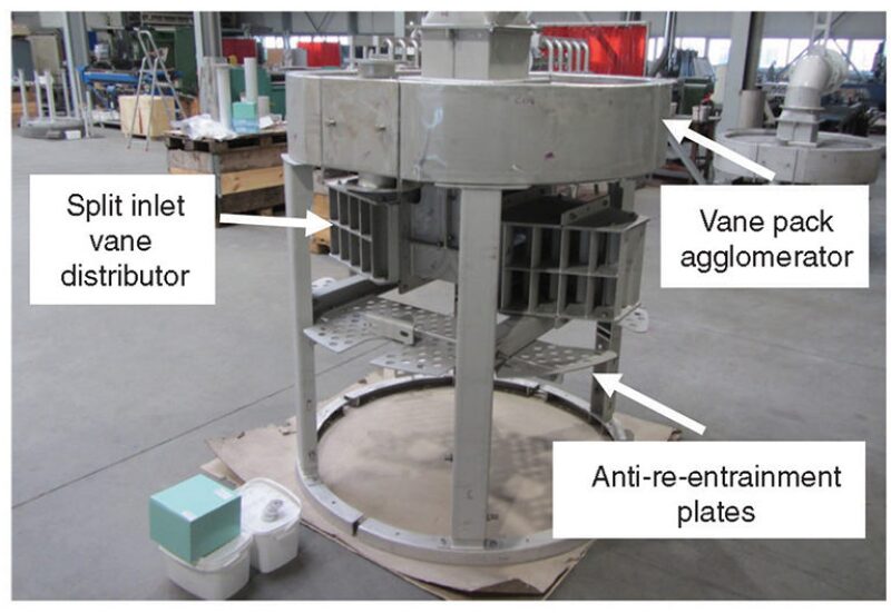
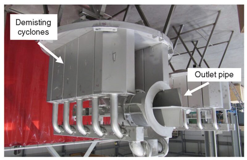
Figs. 3a, 3b, and 3c show the various internals in a dry fit condition. The photo in Fig. 3c is upside down to show the actual orientation of the cyclones.
All the internals were designed to be installed through an 18-in. manway. The existing internals were removed by either unbolting or cutting. Sufficient original metal supports welded to the vessel were left intact to allow bolt-up and installation of the new internals without welding on the vessel shell, which eliminated the need for repeat hydrotesting. Once the vessel was cleaned and readyfor entry, the removal of existing internals and installation of new ones were completed in approximately 14 days.
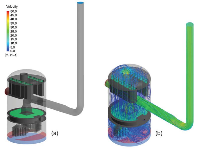
Fig. 4 shows flow paths determined by computational fluid dynamics modeling of the gas flow inside the scrubber, including some of the inlet piping. The inlet pipe high velocities are reduced as expected in the vane-type inlet. The gas flows downward and swirls around before flowing upward relatively uniformly through the vane agglomerator and demisting cyclones, partially due to the high pressure drop across the cyclones.
When looking at Figs. 2 and 3, three things may come to mind.
- “Wow, that’s a lot of steel!”
- “Is this overkill?”
- “It is a complicated installation.”
So, let us look at the reasons behind the design.
- Yes, it is a lot of steel, but it is what is required to support the internals, especially since welding to the vessel shell was not desirable because recertification would be required and the existing supports had to be used. Revamps are not simply plug and play.
- Is this overkill? Maybe. The vane pack agglomerator could have been left out, but the cost was low compared to estimated benefits. Additionally, the scrubber revamp was not a critical path item, so there was time to install the vane pack without extending the platform shutdown.
- Yes, it is a complicated installation, which is a driver for having the vendor technicians either do the installation or inspect/coordinate the installation.
Performance
With the original scrubber design, there was a continuous crude oil carry-over of approximately 20 US gal/D, and much higher volumes getting through the scrubber and filter separator into the glycol system during process upsets. After the modifications, the scrubber effectively prevented crude oil from getting to the glycol system, as indicated during operations when little, if any, crude oil was removed from the glycol system on a daily basis.
In addition, during upset conditions, the scrubber removed so much liquid that the bottleneck was now the liquid drainage system from the scrubber. The scrubber shut down on high levels of liquid, effectively protecting the glycol system.
An upset event is depicted in Fig. 5 with a side-by-side comparison of the original and modified designs. As mentioned earlier, there are two gas trains, each consisting of a scrubber, GC, and filter separator, which then recombine heading into the glycol dehydration system. Scrubber B was modified and Scrubber A remained unchanged.
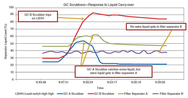
During an upset of high liquid carry-over from the production separator, Fig. 5 shows the level response of the scrubbers and filter separators. Scrubber A and its downstream filter separator A show a modest increase in liquid level. Scrubber B level shows more than double the response of Scrubber A and shuts down on high level due to the undersized liquid outlet valving. The accompanying filter separator B shows no change in liquid level due to liquid being efficiently removed in the upstream scrubber.
Summary
An underperforming scrubber and options to improve its separation efficiency are discussed. Performance data before and after scrubber modification are summarized, showing that the changes were highly successful. Lessons learned from this retrofit may be applied to debottlenecking of scrubbers and separators and also to the design of new facilities in order to avoid these types of retrofit projects later on. OGF
For Further Reading
Chin, R. W. 2015. The Savvy Separator Series: Part 2. The Effect of Inlet Geometries on Flow Distribution. Oil and Gas Fac 4 (4): 26–31.

Robert Chin is a cofounder and past chair of the SPE Separations Technology Section, past chair of the SPE Gulf Coast Section’s Projects, Facilities, and Construction (PFC) study group, a member of the SPE Annual Technical Conference and Exhibition’s PFC paper selection committees, and the author of Chapter 3, “Oil and Gas Separators,” in the SPE Petroleum Engineering Handbook, Volume III, Facilities and Construction Engineering. Chin is a consultant and cofounder of Padden Engineering. He retired from Shell last year. He joined the company in 1981 and conducted advanced research on multiphase flow, leak detection, and separations. In 1999, he left the company to form a separator design and supply company. He returned to Shell in 2006 and led teams in facilities for enhanced oil recovery and subsea processing research and development. Chin holds a degree in applied mathematics and a PhD in fluid mechanics from Harvard University. He may be reached at r.w.chin@sbcglobal.net.

Victor van Asperen is a director of the SPE Separations Technology Technical Section. He is the general manager of the Americas division at FMC Technologies Separation Systems. He has 16 years’ experience in the oil and gas industry with primary expertise in continuous deflective separation, process and systems design, sales, business development, management, and research and development. Van Asperen holds an MSc in chemical and biochemical engineering and a professional doctor of engineering degree in process and systems design from the Delft University of Technology. He may be reached at Victor.vanAsperen@fmcti.com.

J.M. Riesenberg is the program chair of the SPE Separations Technology Technical Section. He is a senior process adviser, separations lead, and compact modular processing systems engineering manager at Chevron. He is responsible for the development and qualification of subsea processing technology, and for supporting and troubleshooting the company’s separations technologies. Riesenberg has more than 24 years’ experience in all aspects of process engineering. He also has experience with gas plants, liquefied natural gas, and gas to liquids refinery. He was a member of the committee that revised the separations section of the Gas Processors Suppliers Association’s Engineering Data Book, and the technical advisory committee for the Separations Technology Research Program joint industry project. Riesenberg holds a BS and an MS in chemical engineering from Drexel University in Philadelphia. He may be reached at JRiesenberg@chevron.com.
Graham McVinnie is the leader of the process engineering team at Shell. He has 21 years’ experience in the upstream oil and gas industry. Before joining Shell, he worked for 6 years at a process engineering consultancy in the UK and Australia. Previously, McVinnie has worked in operations support for four deepwater production facilities in the US Gulf of Mexico and Brazil, as a concept engineer and development planner for new field developments in the Middle East and Africa, and supported gas plant and pipeline operations in the United Kingdom. He holds a bachelor’s degree in chemical engineering from Heriot-Watt University and may be reached at Graham.McVinnie@shell.com.