
The global need for energy continues to rise with energy consumption expected to increase by 30% from now until 2040. Most of this increase in energy demand is anticipated to come from non-OECD countries, especially China and India, because of strong economic growth. The industrial sector, which includes manufacturing and construction, will account for more than 50% energy demand over this projection period. Although renewable energy and nuclear power are the fastest growing forms of energy, fossil fuels are expected to continue meeting most of world’s energy demand until 2040. Out of all the fossil fuels, oil will remain the largest source of energy, providing one-third of the world’s energy demand through the projection period. This poses a challenge to providing sustainable and cleaner energy at the same time.
The dependence upon fossil fuels has caused a rapid increase in carbon dioxide (CO2) emissions since the industrial revolution. This has resulted in atmospheric CO2 concentration to increase from 300 ppm in 1950s to 410 ppm this year (Fig.1), already causing 1°C of temperature increase above preindustrial levels. This increase has disrupted the global carbon cycle, and the signs of global warming are becoming more pronounced around the world. In case of no action, the global temperature is expected to rise by 4.5°C above the preindustrial temperature level. This will play havoc on the environment, and will result in physical and ecological problems like sea-level rise, extreme weather events, disrupted water supply, and food shortage.
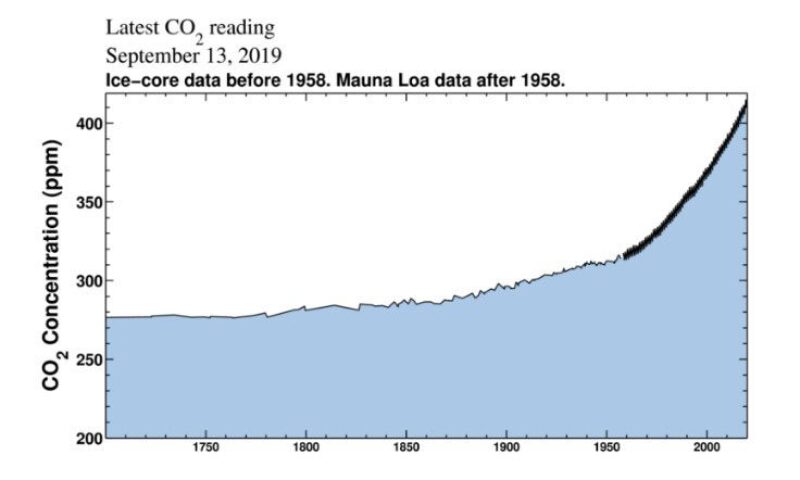
Fig. 1—Atmospheric CO2 concentration measured at Mauna Loa Observatory, Hawaii since 1958. Source: https://www.co2.earth/
The world nations adopted a goal to limit warming to well below 2°C and to pursue efforts to limit the temperature increase to no more than 1.5°C at the United Nations Climate Change conference held in Paris in 2015, generally referred to as “Paris Agreement.” The agreement calls for reduction in emissions from 2020 onwards with an aim to achieve “net-zero” emissions in the second half of the century by striking a balance between anthropogenic emissions and removal by sinks. The Intergovernmental Panel on Climate Change (IPCC) published the Special Report on Global Warming of 1.5°C (SR15) on 8 October 2018. According to the report, with 1.5°C warming, the global mean sea level is projected to rise by 26 cm to 77 cm by 2100. A difference of 10 cm may correspond to 10 million more people living in coastal areas exposed to related risks.
Carbon capture, utilization, and storage (CCUS) is a solution that is capable of significantly reducing emissions from the use of fossil fuels in power generation and industrial applications. It involves technologies to remove CO2 from flue gas and atmosphere, transport it via ship or pipeline, then either use it as a resource to create valuable products or permanently store it deep underground in geologic formations. The carbon capture route depends primarily on CO2 source, and the techniques can be broadly divided into 3 categories: CO2 Absorption, CO2 Adsorption and CO2 Membrane Separation.
[Click to expand image.]
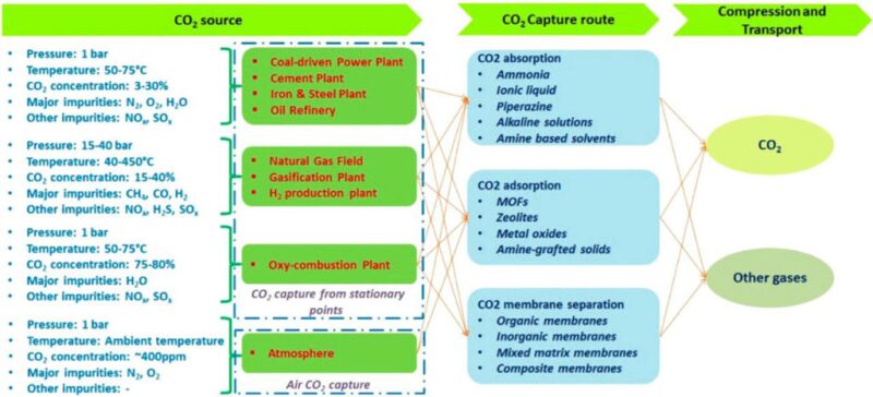
Fig. 2—Summary of the main CO2 sources and existing capture technologies. Source: Yuan, Z., Eden, M.R., Gani, R. Ind. Eng. Chem. Res. 2016, 55, 12, 3383-3419.
Carbon dioxide can then be used as a value-added commodity for commercial purposes to prepare products such as plastic, textile, building material, and agricultural products. CO2 has been successfully used for enhanced oil recovery (EOR) in fields resulting in an additional oil recovery between 15% and 20% of oil initially in place. Fig. 3 shows a variety of possible locations where CO2 can be stored permanently. Different sites have been evaluated globally for storage potential with deep saline aquifers ranking highest out of all options (Table 1). At the end of the CO2 EOR project when the operation becomes uneconomic and the field is decommissioned, effectively all of the CO2 purchased during the project life gets stored, which is referred to as “associated” or “incidental” storage. CO2 EOR is likely the first techno-economic option for addressing the concern of climate change, until other technologies develop further and become more viable. CO2 storage in aquifers, in the context of CCUS, is referred to as “non-associated” storage to distinguish it from storing CO2 through EOR, as both occur in geologic formations.
[Click to epand image.]
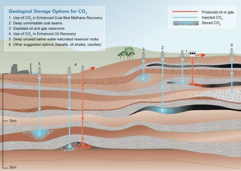
Fig. 3—Geologic storage options for CO2. Source: Intergovernmental Panel on Climate Change, Special Report - Carbon Capture and Storage [IPCC SR CCS].
| Reservoir Type | Lower Estimate of Storage Capacity (Gt CO2) | Upper Estimate of Storage Capacity (Gt CO2) |
|---|---|---|
| Oil and gas fields | 675a | 900a |
| Unminable coal seams (ECBM) | 3–15 | 200 |
| Deep saline formations | 1000 | Uncertain, but possibly 104 |
a These numbers would increase by 25% if "undiscovered" oil and gas fields were included in this assessment.
Table 1—Storage capacity for several geological storage options. Source: IPCC SR CCS.
Though engineered storage solutions are different from natural accumulations of CO2 that have been used for EOR in the USA for last 5 decades, CO2 injected at carefully selected site can be stored underground for 1000s of years. For injection in aquifers, CO2 gets trapped by a combination of four mechanisms in terms of increasing storage security (Fig. 4):
(a) Hydrodynamic/structural/stratigraphic trapping, which occurs because CO2 being less dense than formation brine, rises buoyantly until it encounters a seal that has a capillary entry pressure greater than the buoyancy or hydrodynamic force.
(b) Residual/capillary trapping, which occurs during the counter-current flow of CO2 and formation brine as CO2 migrates up. A relatively more wetting phase enters the pores previously occupied by less-wetting CO2 phase, resulting in CO2 trapping as discontinuous immobile phase.
(c) Solubility/dissolution trapping, which occurs when CO2 comes in contact with formation fluid. Mass transfer occurs with CO2 dissolving into water until an equilibrium state is reached.
(d) Mineral trapping, which occurs because the injected CO2 dissolved in formation brine reacts with formation rock, and gets converted into a stable mineral phase.
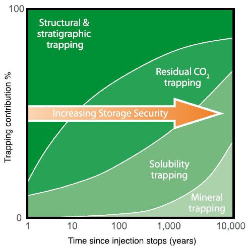
Fig. 4—Relevance of different CO2 trapping mechanisms with respect to time from injection. Source: IPCC SR CCS.
As per the International Energy Agency (IEA), CCUS is expected to contribute to 14% reduction in CO2 emission under the 2°C scenario (Fig. 5). In the “Beyond 2°C” scenario, CCUS will play a far significant role, and anticipated to reduce CO2 emissions by 32%. Without CCUS, the cost of achieving long-term climate goals will be 140% costlier, which is much higher than if other technologies are not available.
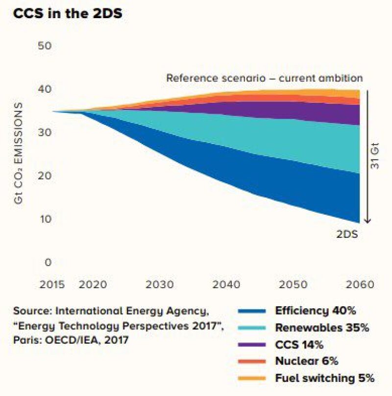
Fig. 5—Contribution of different technologies in CO2 emission reduction. Source: IEA.
Table 2 compares the current CCUS performance with respect to overall goal. The world will need 100s of storage sites by 2050 in order to reduce greenhouse gas emissions.
| Cumulative CO2 Removal Required | 715 Gt CO2 |
| Duration | 20 years |
| CCUS Contribution (14%) | 100 Gt CO2 |
| Annual CCS Contribution | 5 Gt CO2/year |
| CO2 Capture Capacity/Facility | 2 Mt CO2/year |
| Requirement for 20 Years | 2500 Facilities |
| CO2 Disposal Capacity/Field | 5 Mt CO2/year |
| Injection Rate | 250 MMscf/D |
| Requirement for 20 Years | 1000 Fields |
| Current CO2 Capture Capacity | 37 Mt CO2/year |
| Fraction of Required CCS Contribution | 0.7% |
| Fraction of Required CO2 Removal | 0.1% |
Table 2—CCUS Performance With Respect to Target. Data Source: Reports from IPCC, IEA, operators, and others.
There are around 30 small- and large-scale integrated CCS projects in operation or under construction (Fig. 6), including significant ones like the Boundary Dam power station in Canada, Petra Nova in USA, Sleipner and Snøhvit CO2 storage projects in Norway, Abu Dhabi CCS Project for EOR in UAE, and Tuticorin CCU Project in India.
[Click to expand image.]
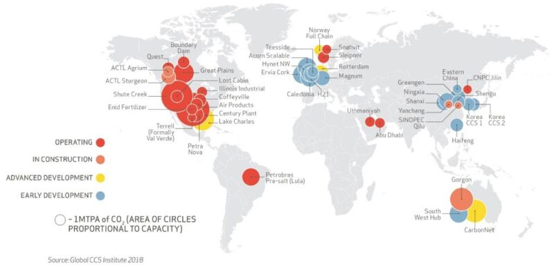
Fig. 6—Operating and planned CCUS projects worldwide. Source: Global CCS Institute. For an interactive map to see the various facilities around the world, click here: https://co2re.co/FacilityData
It is taking long to mature and de-risk the technologies to reduce cost and ensure that there is no subsequent CO2 leakage from reservoir through seals or old wells, and CO2 migration within reservoir to be monitored in a techno-economic way. However, the common understanding worldwide is that CCUS is necessary to meet climate change mitigation goals at the lowest possible cost to society. A combination of tax incentives and research and development demonstration will be critical to accelerate technology development. We are moving at a slower pace, but steadily in the right direction.

Mohan Sharma is a reservoir engineer with Resoptima and is based in Stavanger, Norway. He holds a PhD in petroleum technology from the National IOR Centre of Norway at University of Stavanger. He worked in an international collaboration between seven universities and five oil companies on a project demonstrating large-scale CO2 enhanced oil recovery and storage using a field pilot. Sharma holds an MS degree from Texas A&M University and a BTech degree from Indian School of Mines, both in petroleum engineering. He is an SPE member since 2010.
[The article was sourced from the author by TWA Editor Jaspreet Singh Sachdeva.]
Related Multimedia
Global CCS Institute: 2018 CCS Readiness and Indicator