
The Macondo blowout in the Gulf of Mexico in 2010 represents a game changer in the upstream oil industry with a substantial increase in focus on safety as a result. Control was regained over the blowing well through a physical capping operation, but two relief wells were also drilled, ready to intersect and kill the blowing well dynamically, if the capping operation had proved unsuccessful.
As a consequence of this, every oil company that intends to drill wells offshore, needs to be a member of a capping stack consortium, with access to a capping stack in the event of an uncontrolled flow situation. There are however, a range of situations where a capping stack is incapable of mitigating the situation. It is for instance impossible to cap a blowout if the well has broached around the wellhead, or if the combination of a high-rate blowout and shallow waters creates a situation where the plume prevents marine operations directly above the wellhead.
Read here How Offshore Capping Stacks Work
The ultimate method to kill a blowout if all else fails, is by drilling a relief well that intersects the blowing well, then injecting mud at high rate until the combination of increased frictional pressure and mud weight stops the flow of hydrocarbons from the reservoir entering into the well. This is called a “dynamic kill” and follows the same principle as is applied when drilling a pilot hole to enable increased equivalent circulating density to stop a shallow gas flow when drilling a top hole without blowout preventer. Seeing as this is the last line of defense, it is of utmost importance that proper contingency work has been done upfront to ensure that a hypothetic, yet potential blowout can be killed dynamically through a relief well.
Blowout Potential
The flow rate of a well is mainly governed by two factors, the inflow and outflow potential. Inflow is the reservoir’s ability to deliver hydrocarbons, and the outflow is the friction and size of the flow path. Any steady state production optimization simulator can be used to accurately estimate a blowout flow rate. Altering the inflow potential is difficult; the only effective method is to limit the net pay discovered, i.e., the distance drilled into the reservoir. Restricting the outflow is easily done by, for example, applying a smaller inside-diameter (ID) casing string.
Kill Potential
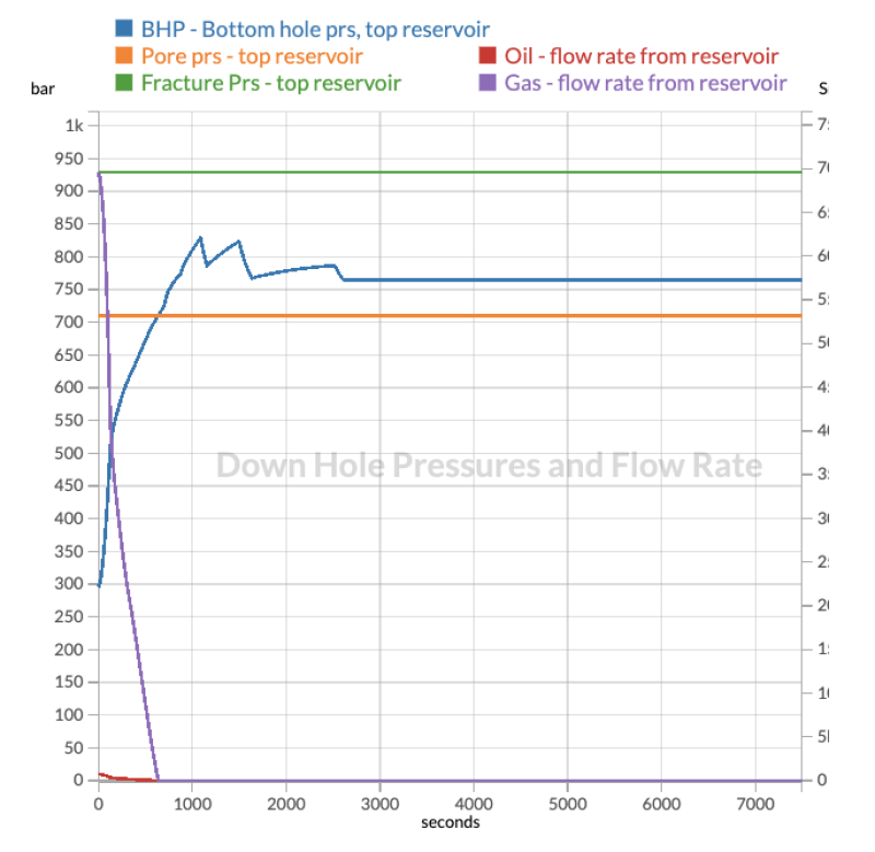
In order to successfully locate and intersect a blowing well with a relief well, steel must be present at the intersection point as a magnetic tool is being used for the ranging process. Hence, for the cases where a blowout occurs when the drill pipe is out of the hole, the intersection must be performed at the deepest casing shoe. A transient simulator is used to simulate and calculate the mud weight and pumping rate which are required to stop the flow of hydrocarbons into the wellbore of the blowing well. This is a relatively complex operation as the reservoir pressure needs to be exceeded, while at the same time, not exceeding the fracture gradient which could lead to loss of mud column and the well potentially kicking off again. Again, the casing configuration will influence on the blowout rates, but also on the required mud weight and pumping rate for the dynamic kill operation. A smaller ID casing string will yield higher pressure loss during the dynamic kill, which again will lower the required pumping rate. See Fig. 1.
Relief Well Design
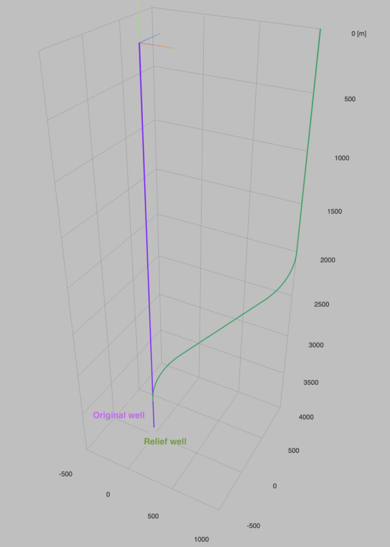
While designing the trajectory of a relief well, one must follow a different strategy than when designing an ordinary exploration or production well. The surface location must be at a certain distance from the blowing well to avoid toxic gases, burning oil slick etc., and it should be placed perpendicular to wind and current direction. The location should however not be too far away from the blowing well as it would complicate the ranging process, since the well needs to approach the blowing well at a certain distance above the planned intersection point. The angle should preferably not exceed 60 degrees in order to be able to run the ranging tool on wireline. See Fig. 2.
Kill Operation
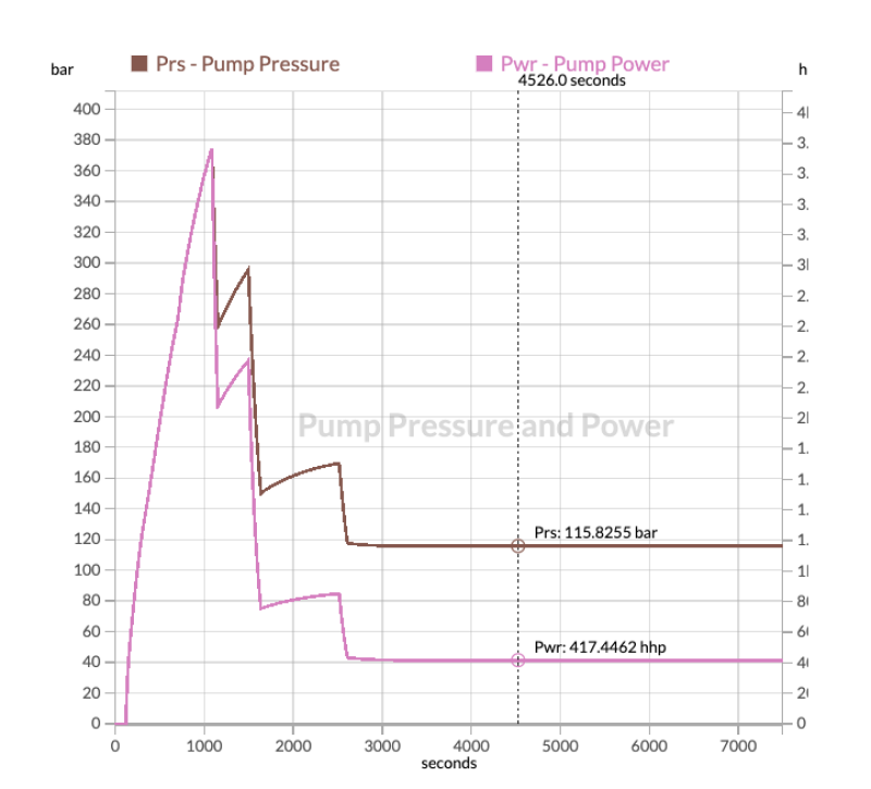
After successful intersection, kill mud is pumped at the rate established during the kill simulations, down the relief well into the blowing wellbore. It is now very important that the rig pumps on the relief well rig is capable of delivering the required rate at the required pumping pressure. The pressure is highly dependent on the configuration of the relief well and it is therefore vital that proper contingency work is done during planning of the well to ensure that the kill rates required can be delivered by a rig available in the area. See Fig 3.
Blowout and Kill Simulations as Part of the Well Design Process
Up until now, blowout and kill simulations have mainly been performed by expert consultancy companies. This has restricted the contingency planning to very few wells, mainly exploration wells with high expected pressure. History has shown though, that blowouts also occur frequently on other types of wells, such as production wells in known areas. It is also a myth that blowouts only occur in high-pressure wells; the Montara blowout offshore Australia occurred from a normally pressured formation where the drilling operations were finished and the well was about to be completed. Being able to investigate the blowout and kill potential automatically on every well as part of the well construction process is therefore an opportunity to increase safety awareness among drilling engineers and put more focus on all aspects of well design, not only for preventing an incident but also putting focus on the consequences of a potential incident. It is strongly recommended that all drilling engineers involved in well construction should increase their knowledge of the mechanisms behind uncontrolled flow, the methods available to mitigate the consequences, and the tools available to design a solid kill plan.
Along with trajectory, casing, and tubing design, a blowout and kill simulation module should be an integral part of modern well design software. It will enable—once the user has created the well trajectory, performed the casing design, and input the expected fluid and reservoir parameters—to run the blowout and kill analysis simulations by the push of one button.
Running Blowout and Kill Simulations Internally
It is very common to use consultants for blowout and kill contingency planning. These are highly skilled experts with experience from live incidents. There is of course a cost associated with this, and rerunning simulations with new data or running sensitivities is expensive and time consuming. As a result of this , oil companies very often limit the blowout and kill contingency work to exploration wells, or wells they assume may be difficult to kill in the event of a blowout. Neither the Macondo nor the Montara blowouts had been subject to blowout and kill simulations prior to the incidents.
The Montara blowout was dynamically killed through a relief well at a mud weight and pumping rate that were on the very limit of what the relief well rig could deliver. Montara was a low-pressure well. Conducting a blowout and kill simulation study up front would have made the drilling engineers aware of the challenges connected with stopping a blowout from this well. Additionally, it shows that all wells have a potential to be difficult to kill in the event of a blowout, not only high-pressure/high-temperature exploration wells.
Hence, having the opportunity to run internal blowout and kill simulations as part of the well construction software package has many advantages for the oil companies:
Ability to run iterations fast such as investigating the effect on blowout and kill rates by using different casing sizes and setting points
Ability to run blowout and kill simulations on all wells, not only exploration wells or certain selected production wells
Seamless integration with other modules, e.g., how changing casing design for blowout purposes influence kick tolerance
Instant update of all modules, e.g., changing the water depth, casing shoe depth, or pore pressure will immediately be updated in the blowout and kill module, making the updated simulation process fast and effective
Creating knowledge and promoting safety awareness among the drilling engineers
Further Recommended Reading
Rygg, O.B. "Well control evaluation as an integral part of well design." IADC Well Control Conference Europe, Amsterdam 9−10 April 2008.
Rygg, O.B. "The necessity of modelling in contingency planning and emergency well control response." IADC International Well Control Conference & Exhibition, Singapore 8−9 November 2005.
Oskarsen, Wright, Rygg, Selbekk, and Allcorn. "A Case Study in Relief-Well Drilling Using a Modified Driller’s Method as a Well-Intervention Alternative to Bullheading." IADC Well Control Middle East 2008 Conference & Exhibition, 2−3 December 2008, Muscat, Oman.

Thomas Selbekk is chief revenue officer at Oliasoft, a Norwegian company with headquarters in Oslo. He holds an MSc in petroleum engineering from Norwegian Institute of Technology (NTH) in Trondheim and has worked in the oil industry since 1990. Before joining Oliasoft, he worked 16 years as a blowout and kill expert with Add Energy, and was central in the kill team combatting the Macondo blowout in the Gulf of Mexico in 2010.
[The article was sourced from the author by TWA editor-in-chief Asif Zafar.]