Conventional drilling through lower intermediate intervals in the southern portion of the Alpine field on Alaska’s North Slope has posed significant challenges. While unstable shale sections can be drilled without significant issues, hole collapse has caused difficulties while tripping out of hole and running casings. In 2011, a new steerable-drilling-liner system was deployed in the field. This paper provides insights into the new technology and the field-trial program.
Introduction
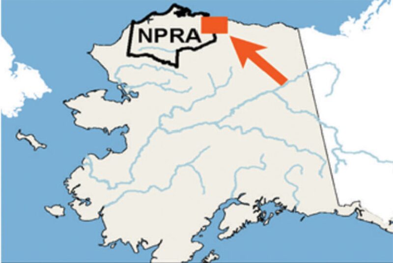
The Alpine field, which came online in 2000, lies near the environmentally sensitive shoreline of the Arctic Ocean on the North Slope of Alaska (Fig. 1 above). It is the westernmost of the current North Slope producing fields and straddles the border of the National Petroleum Reserve—Alaska. The field was developed without a permanent road connection to the existing North Slope infrastructure, to address environmental and indigenous-community concerns. Much of the resupply effort for the roadless period is accomplished during the ice-road season. Field development has progressed from near-pad targets to higher-departure wells in a 6,700-ft-true-vertical-depth reservoir section that has introduced drilling challenges.
Background
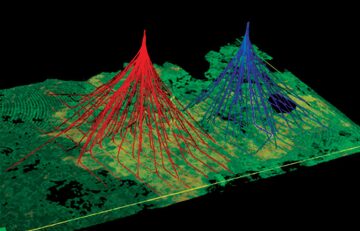
The development of the Alpine reservoir has progressed as an alternating horizontal-producer/-injector pattern for best recovery efficiency (Fig. 2). As field-pad development advanced southward, it was determined that a shale package had thickened in this direction. This thickening, compounded with progressively higher sail angles required to reach points at higher departures, led to issues that affected efficient running and cementing of intermediate liners. New techniques involving higher mud weights and managed-pressure drilling were attempted with limited success.
The authors learned of a steerable-drilling-liner technology that was being developed and deployed offshore Norway to drill through and complete beyond troublesome hole sections. This system was researched, and a case was made to develop and deploy it in the Alpine field in Alaska. (For the details of the related feasibility study, please see the complete paper.)
Deploying new technology in a remote, seasonally roadless Arctic development was no small commitment. Initial deployment plans used nonrotating torque reducers, premium liner connections to ensure integrity through multiple rotations in tortuous hole paths, robust solid centralizers proved in casing-drilling applications, and drilling-dynamics sensors placed above and below the liner to provide recorded and real-time data.
A four-well, progressive, directionally complex pilot program was assigned by the resource asset for two reasons. First, it was not cost-effective to ship specialized equipment over ice roads for a single well project. Second, it was deemed important that the system be given a fair trial, because it could be a key to future development potential in the area. The technology could enable completion of high-departure wells in an unstable overburden where the environmental sensitivity of the area precludes the placement of more drilling pads.
Steerable-Drilling-Liner-Service Overview
The steerable-drilling-liner service combines an advanced rotary closed-loop system and liner drilling. The advanced rotary-steerable system is used in combination with the drilling power of a precontoured modular motor that provides power for the pilot and reamer bits. The system consists of a retrievable and changeable inner string and a liner string connected by a modified running tool. Because the liner is isolated from the reamer shoe, the liner can rotate at much lower rates than the pilot and reamer bits. This design reduces the load on the liner. (For a discussion of the steerable-drilling-liner assembly and its parts, please see the complete paper.)
Directionally, the steerable-drilling-liner platform behaves like a regular rotary-steerable system. The short-stickout pilot bottomhole assembly (BHA) provides the ability to control and steer the system to a required direction for optimal wellbore placement.
The steerable-drilling-liner technology is designed to provide access to reservoirs that present challenging downhole environments that can drive up nonproductive-time (NPT) costs, thereby enabling optimized reservoir recovery. Such downhole environments include, but are not limited to, moving and swelling formations, loss and thief zones, low-pressure zones, and depleted and unstable formations. Running liner while drilling eliminates all NPT associated with additional reaming/circulating, cleanout runs before casing runs, and reaming casing to bottom in some cases.
Torque-and-Drag Modeling
A wide range of friction factors (0.2–0.4) was considered in modeling the torque and drag. There was a concern that torque values would exceed the rig topdrive capacity and the drillpipe-makeup torques. The objective was to cover all possible friction factors that might be encountered while drilling. Additionally, using the upper range of friction factors, the authors sought to estimate the torque required to break static friction should operations be interrupted, and rotation stopped, for an extended period of time.
Results show that the torque required to reach total depth exceeds the topdrive capability for Well Profile A and is at the limit for Well Profile B. The results indicated that it would be challenging to use this technology in Alpine applications without implementing a torque-reduction technique. At this point, after a careful review of available options, torque reducers were considered and nonrotating drillpipe protectors (NRDPPs) were selected. Modeling results indicated that incorporating NRDPPs reduced the torque to reach total depth below operational limits of the rig. It was recommended that higher-torque-rated drillpipe be used for the project, or at least used in the top section of the hole.
For a discussion of the hydraulics modeling, please see the complete paper.
Drilling Operations
To date, the first two wells of the pilot program have been drilled with the steerable-drilling-liner system. Both wells have focused on testing the hardware of the system, verifying modeling results and directional capability in “friendly” rocks.
The first well tested the build capability in a shortened shale section of 643‑ft measured depth (MD) with a 1,044-ft, 7-in. liner section. The system was able to easily achieve the 17° of build over the section with up to 5°/100-ft doglegs against a plan of 3°/100 ft. The excessively long liner lap was planned to meet regulatory expectations and compensate for the uncertainty of the top of the reservoir section.
The second well tested build-and-turn capability in a 1,657-ft-MD shale section with a 2,067-ft, 7-in. liner section. The system easily achieved a 24° build and 31° turn, with 5°/100‑ft doglegs where needed against a 3°/100-ft plan.
Both wells were drilled with a glycol-inhibited, freshwater-based, low-solids, nondispersed system. A lesson from the first well was to eliminate an asphaltene black product that had typically been used in these well sections. The product had a tendency to create large asphaltic chunks of shale debris in the mud system that interfered with some critical placement profiles of the system. After removal of this product, the second well was drilled without drilling-fluid issues. Predrilling hydraulics modeling proved accurate for the system. Adequate hole cleaning was achieved above and below the liner during drilling and was confirmed with post-drilling precautionary sweeps of liner-top areas.
The most significant finding of the system during the first two deployments was the slower-than-anticipated rates of penetration (ROPs). ROPs averaged 12 and 15 ft/hr, respectively. The anticipated ROP was 40 ft/hr. This performance led to a complete redesign of the reamer shoe for the next deployment. It was also determined, from downhole dynamic-drilling-data recorders, that the nonrotating torque reducers required in the drillstring to ensure achievement of total depth with an undersized topdrive were inhibiting weight transfer. This was mitigated with the installation of a larger topdrive and a high-torque string of drillpipe. Future torque-reduction tools will be run for casing protection only. The slower-than-anticipated ROPs did enable system hardware to be tested in drilling conditions for 130 hours without failure of electronics or liner connections.
While torque and drag were large concerns when vetting the project and its viability, preproject modeling proved accurate after the first two deployments. The 1,000-ft, 7-in. liner added 4,000 lbf‑ft of torque to the system, as modeled, and the 2,000-ft liner added 5,000 lbf-ft of torque to the system. The results verified that cased and openhole friction factors determined for standard BHAs were applicable to the liner system when new outer diameters and complete-system (inner- and outer-string) weights were considered.
The final modification to the drilling system was applied to the quick-connect mechanism that mated the 7-in. liner to the 4-in. inner string. It was determined that the original set-screw design was inadequate to hold the cap in place during drilling operations after a failure on the second well. This issue was eliminated by placement of stop blocks in the cap and lower housing where the components meet when made up.
Cementing Operations
Although the first two pilot wells were cemented and passed tests required by local regulations to confirm integrity, the jobs were not flawless. The first well used an inner-string cementing system featuring two hydraulic components actuated with two separate balls. In this first use of the cementing system with the new steerable-drilling-liner technology, the amount of complexity proved to be excessive, resulting in the failure of multiple components in the string and requiring a remedial cement job. The remedial job was pumped at lower-than-planned but effective rates, given the time between the trips required for cement placement and concerns about the hole packing off. The second-well deployment attempted to simplify the cementing equipment with the elimination of the inner string and with cement placement achieved with the liner-wiper plug and drillpipe dart of a standard cement job. The job failed because packoff occurred at the planned cementing rate of 6 bbl/min.
Attempts to regain circulation at rates greater than 1 bbl/min failed. Given this low rate, an inner string was run with a cement retainer and 50 bbl of cement was placed successfully behind the pipe at 1 bbl/min, with an ongoing concern about packoff because of the amount of time required for trips and cement preparation.
The next deployment will use a newly designed cementing string that will eliminate hydraulically set tools but will have the flexibility of an inner string and retainer at the liner shoe with the first equipment run. Cement will be pumped at a maximum rate of 4 bbl/min, which was the successful rate of the first job. It is notable that even with the large amounts of time between drilling and cementing operations, there has always been the capability of pumping with returns in the problematic shale section. This was not expected, even in the “friendlier” pilot area of the field.
This article, written by JPT Technology Editor Chris Carpenter, contains highlights of paper SPE 168044, “First Field Testing of a New Rotary-Steerable-Drilling-Liner Technology on Alaska’s North Slope,” by Greg Hobbs, Rob Stinson, and Chip Alvord, ConocoPhillips, and Okechukwu N. Anyanwu, Christian Klotz, and Muntasar Mohammad, Baker Hughes, prepared for the 2014 IADC/SPE Drilling Conference and Exhibition, Fort Worth, Texas, USA, 4–6 March. The paper has not been peer reviewed.