
The Piceance basin in western Colorado is a long-term play expected to produce for another 20 years or more. Given this extended time horizon, the operator implemented a permanent and centralized water-management infrastructure to control costs and improve profitability. The role of the centralized water-management facility (CWMF) is to treat water produced from natural-gas wells; recover oil and condensate; operate within federal, state, and county regulations; and consistently provide high-quality treated water for hydraulic-fracturing operations and disposal.
Background
Properly designed, implemented, and operated water-management facilities (WMFs) provide the means for controlling water-movement costs. WMFs also allow for predictable operations and provide a consistent high-quality water product on demand for hydraulic fracturing. Three types of WMFs will be discussed in this paper (these can be permanent or temporary):
- Centralized pumping stations for water transfer
- Pipelines
- Centralized water-treatment facilities
Once it is determined that a facility is needed, the decision to build a permanent or a temporary facility is driven primarily by economics. The operator needs to complete an economic analysis comparing the total cost of building a permanent facility with the cost of using contract services and rented equipment to accommodate the business need. For a discussion of cost analysis in this context, please see the complete paper.
Pipeline Facilities and Infrastructure
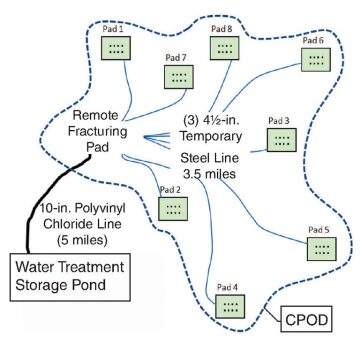
Once the boundaries of the natural-gas-producing zones are established, the operator needs to plan and build pipeline infrastructure and begin the transition away from water hauling. Drilling and completing multiwell pads require high-volume, efficient, and cost-effective water movement. In the Piceance basin, operators use a technique called remote fracturing in which the equipment for completions is set up on one pad and all the well pads within a 3.5-mile radius are fractured from that single pad (Fig. 1). The remote-fracturing pad and surrounding well-pad arrangement are designated a centralized plan of development (CPOD).
Pipeline Planning and Development
In the Piceance basin, the most efficient way to move water for hydraulic fracturing and flowback is to build a water-pipeline loop through and around the area to be developed. In Fig. 2 above, two water-line loops are shown with a CWMF located between each loop. CPODs will be planned all around the loop; storage pits and transfer pumps can be installed and tied in anywhere around the loop, as needed. Water can flow in either direction around the loop. Use of 10-in.-inner-diameter or larger polyvinyl chloride pipe in the loop infrastructure will allow water-flow rates in the range of 25 to 50 bbl/min to and from the CPOD and remote-fracturing pad. With this high flow rate, wells can be completed very efficiently, with no water-delivery delays, and the number of water-storage tanks on the pad is reduced greatly.
Produced-Water Recycle/Reuse Strategy and Disposal of Excess Water
Once a well is completed, the produced water from flowback is routed to a tank battery located next to the produced-water storage pit. At the tank battery, produced water is routed through a gun barrel to separate any free oil, then flows to the pit for temporary storage. At this point, the produced water in the pit is ready to be reused for the next fracturing operation. The storage pit is tied into the water-line-loop infrastructure, and produced water can be moved easily to the next fracturing operation.
As the natural-gas asset is developed, the number of producing wells increases and the volume of produced water from producing wells continues to grow. If the price of natural gas remains strong, operators will maintain an aggressive drilling program. In the Piceance basin, the growing volume of produced water from producing wells is recycled for use in completions. The natural-gas market peaked in 2008, and dropping rig counts created an excess of produced water. Excess water is disposed of by evaporation, by injecting, or by hauling it to a commercial third-party disposal facility. The water-loop infrastructure is used to move water to company-owned disposal facilities.
Understanding the CWMF
Produced water is either piped or trucked to the CWMF. Once the water-loop infrastructure is installed, most produced water will be piped to the CWMF. Trucking to the CWMF should apply only to outlying pads and to producing wells that are not tied in to the water loop.
In Colorado, the Colorado Department of Health and Environment (CDHE) controls volatile-organic-compound (VOC) air emissions related to oil and gas operations and facilities. All CWMFs, and any storage pond associated with a CWMF, must be permitted through the CDHE and must comply with VOC-emission limits established by the CDHE. CWMF processes must be monitored and routinely tested to ensure proper function and to make process adjustments (please see the complete paper for a discussion of such tests).
Primary Oil Separation by Use of High-Efficiency Skim Tanks
Free-oil separation is the first step in produced-water treatment and is accomplished with high-efficiency skim tanks. Gas wells in the Piceance basin yield a 58 °API condensate. This light oil tends to separate fairly quickly; however, with any agitation, it is also easily sheared into smaller droplet sizes that do not separate easily.
When bringing water into the skim tank, one must avoid any agitation or mixing. It is particularly important to avoid pumping or piping configurations in the facilities that cause the water to drop in the manner of a waterfall. An ideal approach is to build the facility on naturally sloping terrain that allows the use of gravity to move the water through the facility.
The following key skim-tank-design considerations are discussed in detail in the complete paper:
- Maintaining constant oil/water interface in the tank
- Bringing water into the tank immediately below the oil/water interface
- Using a baffle to prevent short-circuit water flow
- Optimizing retention time
Secondary Oil Separation by Use of Dissolved-Air Flotation (DAF)
A DAF process is used for removing dissolved hydrocarbons and suspended solids coated with hydrocarbons. The DAF unit is a stainless-steel rectangular vessel. The use of coagulant and polymer chemicals is necessary for successful total-suspended-solids (TSS) removal. Water enters on the lower left and flows into the bottom of the first of two chemical-mixing zones. Coagulant is added immediately upstream of this first zone. TSS particles will have a negative molecular charge. The cationic coagulant (positively charged) provides a destabilizing effect on the negatively charged particles in the water. Before coagulant treatment, particles repel each other, but after coagulant treatment, particles begin to bind and form a small flocculation because of the change in molecular charge. Mixing energy in the coagulant zone is generally kept fairly high to provide sufficient contact of the coagulant with all the solid particles and hydrocarbon content. A coagulant dosage of approximately 80 ppm is the typical operating dosage, but it is dependent on incoming-water quality. From the coagulant zone, water passes over the top of a weir and into the flocculation zone, where an anionic (negatively charged) polymer is added. Dosage of the polymer is typically in the 25-ppm range for maximum separation effectiveness. Over-/undermixing of the polymer can have an effect on how well the particles bind.
The water is now chemically treated and begins to move through the main body, or clarifier section, of the DAF unit. At this point, the water will pass through a rising stream of microbubbles. These microbubbles adhere to the solid particles in the water, reducing the specific gravity of the solids and allowing them to freely float to the surface. To produce microbubbles, compressed air is injected into the recycle stream on the discharge side of the recycle pump. The resulting air/water mixture flows into the saturation chamber, where it is exposed to great turbulence. This turbulence is used to maximize the amount of air that dissolves in the recycle stream. From here, the stream flows through a pressure-reducing valve immediately before being delivered into the clarifier section of the DAF unit.
Solids that float to the surface are then skimmed off the top of the water by a continuous skimmer paddle; they enter into the froth trough and then are routed to emulsion tanks for further treating. The clean water flows over a weir and is discharged into a holding pond.
Chemical Selection for Optimizing DAF Performance
The DAF chemical-treatment program is designed to maximize the removal of suspended solids (turbidity) and residual hydrocarbons. Influent-water quality can be highly variable, depending on the source of the produced water and flowback water. This includes variations in TSS, hydrocarbon concentration, biological components, and miscellaneous chemical compositions from upstream well-completion and production treatment.
While there is a close relationship between turbidity reduction and the associated hydrocarbon reduction, it is not always directly proportional. Turbidity monitoring is used as the primary means of routine daily effluent monitoring. More-detailed laboratory analysis is performed on a regularly scheduled basis to confirm all effluent values.
Influent-Water Quality vs. Chemical Dosage. In general, higher-TSS water will typically relate to higher chemical demand. However, it is not uncommon to see water with higher turbidities [500–800 nephelometric turbidity units (NTU)] have lower chemical demand than lower-turbidity waters (less than 300 NTU). This relates to the zeta-potential (surface charge) and the amount of repulsion of the individual solids/colloids in the water. The higher the zeta-potential, the greater the repulsion properties the particles will have and the less likely will be their tendency to agglomerate. Surfactants commonly used in well production can interfere with the DAF chemistry because of the effects of reduced surface tension and the emulsified effects that result. In these situations, an increase in the coagulant dosage will normally provide improved water clarity.
Coagulant. Jar testing was performed with several organic and inorganic coagulants in combination with emulsion flocculant polymers (anionic and cationic). The coagulant chemistries can be segmented into organic and inorganic. The coagulant is required to destabilize (neutralize) the negatively charged particulates and colloids so they begin to join and form a small flocculation during the initial phase of solids separation.
The use of an aluminum-based coagulant provides the best overall liquid/solids separation on 90% of the various water sources vs. other inorganic or organic coagulants.
Polymer for Flocculation. The flocculant polymer is a high-charge, high-molecular-weight, anionic-emulsion polymer. This was shown to provide the most effective floc formation, solids separation, and water clarity. Several anionic products with various charges and molecular weights were initially tested on the bench at various dosages. Other parameters that were evaluated include chemical-mixing time, mixing energy, and polymer make-down concentrations. In addition, other flocculation characteristics were evaluated, including reaction time, floc size and strength (shear), flotability, and treated-water clarity.
DAF-Performance Testing. The chemistry that was found to perform the best on the bench was tested in actual DAF operation. The variances of the actual DAF conditions vs. the simulated jar-test conditions include chemical-feed location, mixing energy, mixing-zone-circulation pattern, air effects, and residence/separation time. The overall effects in the DAF unit showed results similar to those seen in the jar testing (please see the complete paper for these test-procedure details). With a properly adjusted DAF and an optimized chemical program, total-petroleum-hydrocarbon readings on the DAF effluent will be in the range of 10–30 ppm.
A detailed discussion of emulsion treating and sludge dewatering can be found in the complete paper.
This article, written by JPT Technology Editor Chris Carpenter, contains highlights of paper SPE 169586, “Strategies and Methods for Centralized Water-Management Facilities in the Piceance Basin,” by Joseph J. Lobato, SPE, WPX Energy Rocky Mountain, and Gary Zolnosky, Chem Treat, prepared for the 2014 SPE Western North American and Rocky Mountain Joint Regional Meeting, Denver, 16–18 April. The paper has not been peer reviewed.