
Conventional high-pressure/high-temperature (HP/HT) packer and bridge-plug technology is generally limited to long-term operation at 15,000 psi and 450°F. A great deal of research-and-development effort has been put into extending performance beyond these limits. Recently, an innovative approach was applied to this problem, with the objectives of increasing these limits and enabling long-term isolation in ultra-HP/HT wells. This approach resulted in the development of an ultra-HP/HT permanent bridge plug for long-term exposure at 25,000‑psi pressure and temperatures of 500°F.
Introduction
The process of completing an ultra-HP/HT well with temperatures approaching 500°F and hydrostatic pressures approaching 35,000 psi is evolving at a rapid pace, and the industry has identified a need for a standalone barrier to isolate the shoe track in these wells. This barrier is required in these applications to mitigate uncertainties related to shoe-track integrity. Historically, bridge plugs for use in ultra-HP/HT applications (greater than 20,000-psi differential pressure and 450°F) have not been available in the marketplace, but the demand for competent, long-term isolation has led to the development of new HP/HT technologies—specifically, ultra-HP/HT bridge plugs.
Recently, an operator of an ultra-HP/HT well identified the need for a bridge plug capable of operation at a 25,000‑psi pressure differential (from above and below) and at 500°F. This bridge plug was required to function in a 6⅝-in. outer diameter (OD) casing over the weight range of 57.58 to 60.1 lbm/ft. Furthermore, the bridge plug had to meet validation and International Organization of Standardization requirements and possess an estimated service life equal to that of the 6⅝-in. casing.
A materials-screening and qualification program was used in the design of the bridge plug. The result was a list of three perfluoroelastomer compounds that were evaluated for various seal configurations. Three metallic alloys were also identified for use in the pressure-containing, structural, gripping, and sealing components in the bridge plug. A surface-treatment-qualification program also identified two coatings for use in combating friction and galling. This effort required 18 months.
Service Life and Materials Stability
The operator had stated the service-life target as being for the life of the liner. A portion of the screening and qualification work was dedicated to assessing the material choices for service life (metallics) and material stability (nonmetallics).
Given that the liner was American Petroleum Institute Grade Q-125, the metallic-material candidates were assessed for service life using the anticipated corrosion performance for the liner. Taking into account the various types of corrosion that were likely to occur, studies were conducted to assess corrosion performance in the areas of uniform corrosion, cracking resistance, and localized corrosion. These studies concluded that, on the basis of all environmental and operational information available, the recommended alloys would experience uniform-corrosion rates lower than those expected for the liner alloy. The conclusion reached for this part of the metallic-materials-qualification program was that all short-listed alloys for bridge-plug components were acceptable in terms of service life.
Nonmetallic-materials stability was estimated with polymer manufacturers’ information and in-house laboratory tests, including but not limited to the manufacturers’ temperature rating, data from legacy applications, and in-house environmental exposure and aging tests. The test program revealed that each perfluoroelastomer compound responded differently in exposure and aging tests, resulting in different conclusions about material stability over time. The test program established that, in a simulated downhole environment, all temperature ratings were higher than 500°F, and thus a margin of safety for temperature stability was established. Further, each compound was confirmed to be stable in oil, amines, hydrogen sulfide, carbon dioxide, and zinc bromide.
Casing-Seal Considerations
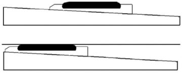
The greatest technical challenge encountered in the design revolved around the sealing member that needed to expand to the casing. There was a limited choice of elastomers that could operate over a long period of time at 500°F. The perfluoroelastomer compounds selected through screening and stability investigations were then assessed in terms of manufacturability and sealing performance. There were many concerns that had to be addressed during the design of the seal to ensure that the best compound was chosen. Not only is the perfluoroelastomer very difficult to mold in larger cross sections, but the material also has elongation limitations that would likely result in the failure of a traditional packing element, as seen in Fig. 1.

It is also widely known that, at elevated temperatures, perfluoroelastomer materials lose rigidity. The loss of rigidity leads to extrusion and ultimately to the failure of the packing element. At 500°F and 25,000 psi, a traditional packing element would therefore require a virtually void-free backup system, and it would also have to be very strong in order to contain rubber. In a traditional packing element, the differential pressure across a bridge plug acts on the rubber and further energizes it. Because of rubber’s viscoelastic nature, rubber exerts a restoring force in every direction. The industry refers to this as rubber pressure. In a traditional bridge-plug design, and at a differential pressure of 25,000 psi, a rubber pressure of approximately 35,000 psi would be expected. Thus, it would be very difficult to contain a perfluoroelastomer packing element under the maximum rated differential pressure of 25,000 psi at 500°F.
In-house material scientists performed extensive testing on multiple elastomers at temperature and at pressure in the various potential well fluids that would be used as part of the screening and stability investigations. Many characteristics were studied, including compression set, thermal set, elongation, and thermal expansion.
Because of the constraints identified earlier in this paper, the design of the sealing member evolved into a new patented casing-seal concept. The casing seal consists of a metal carrier to which the perfluoroelastomer is bonded. An energizing force is applied to the casing seal that expands it to the casing inner diameter (ID) by a conical ramp, as demonstrated in Fig. 2, thus placing it into a sealing position against the casing.
This casing-seal design allowed the design team to consider far more material options when compared with a traditional packing-element system, because of the much smaller cross section and the minimal amount of elongation required to create a seal against the casing.
At these elevated temperatures and pressures, any gap for the rubber to flow through will lead to failure of the seal. Thus, a key design difference between the seal design chosen for the bridge plug and the legacy seal technology was the addition of an integrated backup system that prevents extrusion of the perfluoroelastomer at 500°F. This integrated backup system needed to conform fully to the irregularities along the ID of the as-rolled casing, which is a requirement for prevention of extrusion of the elastomer.
Metallurgy
The operator’s requirement for service life of the tool was for it to be equivalent to that of the liner. Therefore, with one exception, 4XXX-series steels were used. The only noncarbon-steel metal component on the bridge plug is the metal carrier for the casing seal. A seal design that is expanded outward over a cone, such as this design, tends to keep everything round or concentric to the cone over which it is being pressed. The problem with everything expanding out round is that the casing downhole is not going to be perfectly round; thus, there would be gaps between the backup system on the seal and the casing. At the elevated temperature and pressure ratings required on this bridge plug, there would be extrusion of the rubber that would lead to the inability to hold the differential pressure.
Several random sections of casing were examined, and the variance of roundness was concluded to be as high as .070 in. In order for the casing seal to operate reliably at 25,000 psi, its integral backup system would need to conform to all anticipated irregularities in the casing ID.
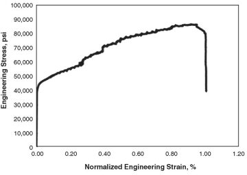
The need for the integrated backup system to conform fully to the irregularities, and the need for the casing seal to expand enough to cover the entire casing range, required the use of an extremely ductile material for the seal carrier to which the perfluoroelastomer would be bonded. A corrosion-resistant alloy was ultimately chosen as the casing-seal carrier material. The material properties of the alloy were confirmed at various temperatures between room temperature and 500°F. Engineering stress-and-strain curves were determined through testing at a third-party metallurgical laboratory. Fig. 3 illustrates the elastic/plastic engineering stress-strain-curve summary for the alloy at 500°F.
For a discussion of the backup system and the development of the setting tool used in this project, please see the complete paper.
Advanced Design Methodology
To reduce development time, finite-element analysis (FEA) was used extensively for design optimization of the casing-seal system. To be considered as a viable design, the following criteria had to be met:
- The equivalent plastic strain in the metal insert and maximum elastic/plastic strain in the seal were measured in all models. The equivalent plastic strain in the metal carrier should not exceed the in-situ allowable plastic strain, and the maximum elastic strain in the seal should not exceed the materials’ in-situ allowable strain.
- The casing seal had to be fully deployed to the casing wall with only the minimum required setting force.
- The casing seal then had to operate, in stable fashion, with a simulated 25,000-psi differential pressure (from both above and below) in combination with simulated hydraulically induced tensile and compressive loads.
- The casing seal had to operate, in stable fashion, without rubber extrusion.
During the casing-seal deployment, the thermal/mechanical coupling FEA was run to assess backup-system stress caused by rubber expansion and seal-OD growth.
Both analyses were repeated until an optimum seal design was achieved. A 3D multibody-contact FEA model ring was performed with as-rolled casing, the optimized casing seal, and the conical expander built in order to identify the minimum setting force. The 2D FEA model assumed the casing ID was perfectly circular, and the 3D multibody-contact FEA model accounted for the as-rolled-casing ID profile with as much as 0.070-in. deviation from nominal ID dimensions.
For this ultra-HP/HT casing-seal system to be used in as-rolled casing, the setting force was known to be far greater than that of a conventional-packing-element system; therefore, it could cause buckling in certain components. Elastic/plastic buckling analysis was then conducted on various components to ensure that buckling was not a failure mode during setting and thereafter.
Test Methodology
The first step in the testing methodology was to conduct component-level tests on the major load-bearing sections of the bridge plug (i.e., the slip/cones and the casing seal). When the results of these tests were deemed satisfactory, the testing methodology evolved to full-scale testing. The bridge plug underwent qualification testing with water and nitrogen to the maximum rating of 25,000‑psi differential (from above and below) at 500°F, inclusive of a thermal cycle representative of the anticipated isolation application. Multiple qualification tests were run on the bridge plug. To further mitigate the risk of failure on the first field installation of the tool before it was released, the test program for the bridge plug also included water and nitrogen testing in an operator-supplied section of as-rolled casing. Finally, to establish reliability, a system-integration test was conducted using all full-scale components intended to be run when installing the bridge plug; in this test, the design margin was confirmed through a test pressure of 26,500 psi using fresh water.
This article, written by JPT Technology Editor Chris Carpenter, contains highlights of paper SPE 166382, “A State-of-the-Art Completion Technological Innovation: The First 25,000-psi, 500°F Permanent Bridge Plug,” by Tony Ruffo, SPE, Guijun Deng, SPE, James Doane, SPE, Gary Anderson, SPE, Douglas Lehr, SPE, and Scott Collins, SPE, Baker Hughes, prepared for the 2013 SPE Annual Technical Conference and Exhibition, New Orleans, 30 September–2 October. The paper has not been peer reviewed.