
This paper reports results of a well-control study for a program to develop a dual-gradient-drilling (DGD) system known as controlled mud pressure (CMP). Conventional well control may not be possible when using dual-gradient systems, because a chokeline full of heavy mud may fracture the formation, making well control a major obstacle to implementing DGD offshore. The project developed several well-control methods, and one was selected for field testing after a risk-assessment process with the operator.
Introduction
While DGD solves many deepwater drilling problems relating to wellbore pressure (please see the complete paper for a discussion of the principles and applications of DGD), it may require new procedures for well control. This depends on water depth and how much the mud weight is increased. New well-control procedures will be necessary because the heavier drilling fluid in the well will exceed the formation’s fracture-pressure gradient if allowed to fill the chokeline and create a full column back to the surface. This potentially dangerous condition can result in formation breakdown and potential loss of well control.
It is also possible to apply DGD without extending casing depth. In this case, DGD will provide increased margins, and in some cases conventional well-control procedures may be applied.
DGD Well Control
Well-control procedures for DGD vary depending on the equipment and the exact nature of the DGD process, but for seafloor subsea-pump-based systems, the basics are well-documented in the literature. CMP uses a subsea pump to return drilling fluid and cuttings exiting the well to the surface. The subsea pump selected by the project is similar to a conventional centrifugal pump, and uses rotating disks to impart energy to the fluid through viscous drag in place of a conventional centrifugal impeller. Before commercial application, a number of tests to demonstrate the CMP DGD system’s abilities are planned in a cased section of an offshore well. In preparation of the scheduled field tests, operators ran simulations using a computer model to prove the system’s performance and provide comparative data for use during the field test. The simulations covered the system’s ability to detect kicks (influxes of formation fluid) and to circulate a kick from the well with precise control of the bottomhole pressure (BHP) using different control scenarios.
Test Setup
Fig. 1 shows a schematic of the field-test equipment. The CMP system uses a special riser joint that integrates the pump and allows access to the riser annulus for the pump suction. During well control and kick circulation, the blowout preventer (BOP) is closed, so a separate line from below the BOP to the pump suction is provided. This line uses one of the annular preventer’s double-block valves to access the well annulus.
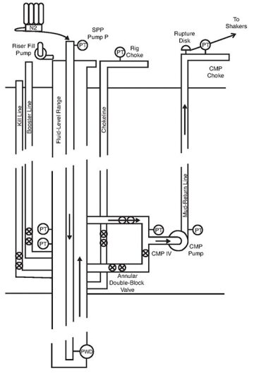
The test will be performed in midwater (approximately 1,000 ft), and the pump can therefore be placed at or near the seafloor. A special CMP choke skid is connected to the output of the flow return line from the pump. This choke and the subsea pump are used to control BHP and expansion of the gas as it exits the mud-return line. A bank of nitrogen bottles are plumbed into the stand-pipe manifold. A ball valve, a flowmeter, and a check valve in the line allow for controlling the flow from the nitrogen bank, measuring the flow, and preventing drilling fluid from filling the nitrogen bottles. This system is used to inject nitrogen kicks while the rig pumps are pumping drilling fluid into the well. The boost line is connected to the cement pump; this system is used to inject liquid kicks into the annulus without the CMP operator’s knowledge. This method will determine the minimum detectable kick size.
A top fill pump is also added to the system. This pump places a fixed volume of mud (e.g., 100 gal/min) into the top of the riser to prevent barite sag and keep the riser fluid moving in a downward direction.
A custom-designed controller integrated into the system operates the subsea pump. The system allows operating the pump in constant-pressure mode on the basis of the pressure in the riser at the suction point; constant-speed mode (manual) on the basis of the speed of the motor driving the subsea pump; and constant BHP or automatic mode, where the BHP is kept constant by adjusting the riser pressure to compensate for equivalent-circulating-density variations with the subsea pump.
The CMP choke is normally 100% open. In a well-control event, the subsea-pump control will switch to pressure control of the standpipe pressure, as in the driller’s method, while the CMP operator controls the choke manually on the basis of parameters available on the control computer/human interface. The operator can graphically display many parameters measured by the system, including critical pressures and the flow rate through the mud-return line from the pump.
Three separate mathematical models calculated critical parameters for the test simulations. The first is a commercially available model, and the other two are operator-developed internal models.
The CMP system being tested circulates the drilling fluid through a disk-type pump and up a separate mud-return line; this includes fluids from kicks. The subsea pump and mud-return line are rated at low pressures when compared to conventional well-control equipment. To keep pressures within the range of the pump and mud-return line, it is important to minimize kicks and thus the pressures needed to control the kicks.
For a discussion of the simulation of the subsea-pump model and the setup and results of kick-detection tests, please see the complete paper.
Influx-Circulation Tests
The next series of tests is intended to determine if a kick can be circulated out from the well in DGD mode while keeping the BHP constant. The target drilling window for BHP for these tests is ±75 psi (±5 bar). The difficulties in keeping BHP constant for this system is the performance of the subsea pump with gas-cut mud and coordinating use of the choke in the top of the mud-return line with the pumps.
Kicks are made by lowering the fluid level in the riser and allowing the drillpipe to experience U-tube dynamics. Nitrogen is then injected to pressurize the drillpipe. The charge pressure in the drillpipe will produce 1-, 4-, and 8-bbl kicks at bit depth. Once the drillpipe is pressurized, the mud pumps are started and the gas is pumped down to the bit, allowing the riser to refill. After the kick has reached the bit, the BOP will be closed and the flow into the subsea pump is routed from the riser to the BOP bypass line. This change also includes slowing the rig mud pumps to the predetermined slow circulation rate. This rate is sufficient to keep the drillpipe from U-tubing, but also sufficiently slow to control the pressure while accommodating gas expansion as it moves up the riser. The pressure to be controlled is the standpipe pressure (SPP). After these actions are completed, the CMP system configuration is set to circulate the kick from the well. Pressure control is achieved by regulating the subsea-pump-module (SPM) speed and adjusting the choke on the mud-return line.
Several considerations had to be accounted for when deciding upon the most practical control strategy. Initially, there is almost no pressure drop over the choke, so this can be used only to add pressure to the SPP by reducing its opening. The SPM can be used to both increase and reduce the SPP. However, when the gas fraction exceeds 20%, the SPM loses all of its leverage and is no longer usable for control. Before this happens, the SPM should be set to idle. Simultaneously with the SPM losing head, the drilling fluid in the mud-return line is being displaced by gas that lightens the hydrostatic head.
Various control schemes were considered as viable options, including the following (further details of each scheme are provided in the complete paper):
- Manual-control/constant-speed mode
- Automatic control by use of a single proportional, integral, and differential (PID) controller
- Automatic control by use of two PID controllers, one for the choke and one for the SPM
- Constant SPM speed
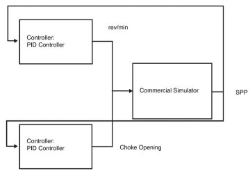
Control Strategy 3 was simulated by use of a commercial transient multiphase simulator. In this strategy, the choke was initially operated manually and was kept fully open while the SPM controls the SPP. When the head from the SPM was reduced to 50% of its expected performance at the given speed, the mode of the SPM controller was set to manual and the output was frozen at the current value. The choke then took over the control of the SPP by changing the controller mode to automatic. The choke could now add the necessary pressure to the SPP to compensate for the loss of hydrostatic head in the mud-return line as the gas was approaching the choke. Note that, at 100% choke opening, the SPP cannot be reduced further because the choke is already fully open. When the SPM regained its leverage, the SPM PID controller was again set to automatic mode while the choke PID controller was set to manual mode and was opened gradually to the full-open position.
A schematic of the control loop is given in Fig. 2. During the simulation, the choke was initially kept fully open while the SPM was controlling the SPP. When the gas fraction downstream of the SPM rose above 15% (22–40 minutes), the output from the PID controller to the SPM was frozen and a PID controller using the choke opening to control the SPP was activated.
Simulations using three different models, two kick sizes, and the aforementioned control methods were run to determine the variation in BHP that would occur as the kick was pumped up the well annulus and mud-return line. These simulations indicate that it is possible to circulate the kick from the well and maintain the constant-BHP requirement.
Summary
The simulations show that DGD and well control are compatible. The kick-detection tests show that even small influx rates from the formation are detectable. In addition, influx volumes up to 8 bbl (kick size measured at bottomhole conditions) can be circulated out of the well safely in dual-gradient mode. In addition, the simulations show that this can be accomplished while controlling the BHP in a range of ±70 psi.
Data from the simulations show that, for ease of detection, the graphical output must use the proper scale to make the influx readily detectable by a human operator. The data also show that both manual and automatic control of the system can be applied to circulate a kick from the well safely. The simulations provide enough data to move forward with field tests as planned.
This article, written by JPT Technology Editor Chris Carpenter, contains highlights of paper OTC 25360, “Dynamic Simulations of New Well-Control Procedures Used To Prepare a Dual-Gradient-System Field Trial,” by J.H. Cohen and R. Stave, Enhanced Drilling, and E. Hauge, J.M. Godhavn, and D.O. Molde, Statoil, prepared for the 2014 Offshore Technology Conference, Houston, 5–8 May. The paper has not been peer reviewed. Copyright 2014 Offshore Technology Conference. Reproduced by permission.