
This paper presents an alternative approach to designing and executing matrix-stimulation treatments in multilayered carbonate reservoirs. The proposed workflow does not rely on damage skin by layer during the design and the execution phases of the treatment. It instead requires a step of determining where the acid must be injected, and at which rate and volume, to meet an objective function. The workflow presented here allows decoupling the questions of optimal placement of a fluid for a given well, the performance of the materials selected, and the treatment schedule considered.
Introduction
Because acid dissolves carbonate formation without damaging reactions, the main challenge in acidizing multilayered carbonate reservoirs is to achieve optimum placement of the stimulating fluid. Heterogeneities such as the inherent dual porosity, high permeability contrasts of carbonate rocks, variable extent of damage, presence of natural fractures, or existence of differential pressure between reservoir layers—which can sometimes feature very large heights or lengths—tend to affect the fluid-injection profile. The uncertainty and often limited knowledge of those various parameters usually complicate the design of carbonate-acidizing treatments, whose outcome very much depends on how well the rock and damage characteristics have been taken into account when selecting the stimulation fluids and how and where those fluids will be pumped into the formation.
Optimum placement is often interpreted as uniform placement of the fluid across the producing interval, and the uniform distribution of the stimulation fluids over the interval has become, over the years, an accepted requirement for successful treatment. However, is it assumed that uniformity of the fluid distribution always represents the optimum fluid placement, regardless of the well conditions and treatment parameters? The question deserves particular attention.
First, it is not necessarily the case that uniform fluid placement results in uniform stimulation along the producing interval, given that the extent of skin reduction is a function not only of the injected volume but also of the local velocity at which the fluid enters the formation. By considering all the aforementioned challenges, and in particular the high heterogeneities of the formation, it is possible to build a reasonable case in which uniform distribution of fluid results in heterogeneous skin distribution along the wellbore.
Furthermore, it is quite possible that injecting the entire volume of treatment fluid in a severely damaged, high-permeability zone to bypass the damage provides a return on investment higher than that allowed by diverting and spending a fraction of the acid treatment on an undamaged low-permeability zone. Aiming for uniform fluid coverage indeed neglects the initial conditions such as extent of damage, which can vary significantly along the wellbore.
Finally, even if uniform stimulation along the wellbore is reached by achieving a constant and negative value of skin along the wellbore, it is not established that it always results in the highest production increase or the best economic returns.
If uniform fluid placement is not the universal optimum-placement strategy, then one may ask whether one may substitute for it with any other rule of thumb. In reality, optimum placement must consider both the treatment’s objective and its constraints. For example, the objective may be to maximize the production of the well or it may be to drain the reservoir as uniformly as possible. A broad range of constraints can also be considered. A nonexhaustive list includes, among others, the volume of acid and the horsepower that can be mobilized, the maximum allowable pressure (both bottomhole and surface), and environmental concerns.
It is of high interest for the stimulation engineer to determine the optimum fluid placement before selecting the placement method and diversion materials and finalizing the treatment design. However, without an optimization tool, it is not possible to determine the optimum placement of fluid before selecting the diversion material. In that case, computer simulations are used to design a treatment to reach an acceptable level of stimulation, but these cannot help in determining whether the solution lies far from the optimal placement and stimulation that could have been achieved within the same set of constraints.
In this paper, we describe a workflow to design and execute a matrix-stimulation treatment so that the treatment results in the optimum placement of the stimulating fluid. The engineer can proceed to selecting the diverting method that will enable the predetermined placement and can design an optimum treatment. We provide examples in which the optimum-placement strategy is not uniform fluid placement along the lateral, and is a function of the objective and constraints.
Methodology
The methodology we present here allows decoupling the questions of optimum placement of a fluid for a given well, the performance of the materials selected, and the treatment schedule considered. The workflow consists of five major steps.
Step 1. This step corresponds to the collection of data regarding all the variables that can affect the placement of the fluid during the injection. A list of the most-often-used data of this kind is given in Table 1 of the complete paper.
It is important to stress that information about the damage consists of its nature only, which is useful to select the proper fluid or additive to remove the damage. However, the quantification of the damage is of secondary importance for Steps 1 through 4.
Step 2. The second step consists of establishing the objective of the treatment. This is the objective that must be reached within the constraints that will be identified in Step 3. Some typical objectives may include
- Maximizing production rate after treatment
- Maximizing hydrocarbon-recovery factor
- Obtaining uniform placement of fluid across all zones
- Obtaining uniform injectivity after treatment (for injector wells)
- Minimizing injection pressure after treatment (for injector wells)
- Reaching specific negative skin values in certain zones (while the fate of other zones may or may not be important)
- Removing damage uniformly, without requirement on the further stimulation of the zone (e.g., reaching damage skin equal to zero in each zone)
The objective function is translated into mathematical terms in the engineering tool to be used in Step 4. It may be formed as any combination of the primary objectives mentioned previously, with various weights to allow the ranking of the objective’s priorities.
Note that the objective function is defined before any consideration of the material to be used to achieve that objective. This separation between the objective of the treatment (which will lead to determining target volume and rate distribution) and the materials and pumping schedule to reach this objective is one of the salient features of the proposed methodology. This is an advantage over simulators in which the engineer performs the tasks of material selection, pumping-schedule definition, and objective optimization simultaneously, without indication of whether the treatment being designed is optimal. This is not an easy task, because relationships between injection rate and stimulation efficiency are not trivial, even in the simple case when only one zone is considered.
Step 3. After having established the objective(s) of the treatment, the next step focuses on identifying the constraints of the treatment. These constitute the boundaries within which the optimization of Step 4 will be performed. Constraints are of various natures. Typical examples include the type of acids that may be used for stimulation and horsepower, pressure, fluid-volume, and cost limits. These constraints need to be translated into mathematical terms to be used with the engineering tool in Step 4.
Step 4. This step aims at determining the volume and rate distributions for injection into each discretized flow unit along the wellbore. Fig. 1 shows an example of a two-zone case in which one flow unit per zone is considered. The flow is computed by a simulator, the characteristics of which are described here.
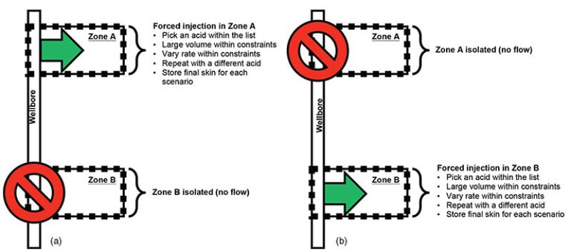
The discretization of the wellbore and formation along the well is made with a resolution of at least one flow unit per zone. Multiple units may be assigned to each zone to improve calculation accuracy when the flow distribution within a given zone may not be uniform (because of gravity effects, for instance). The inputs of the simulator are the pieces of information gathered in Steps 1 through 3. The simulator computes the skin vs. injected volume for various rates of placement and for the chosen fluids, independently, layer by layer. In the two-zone case, as illustrated in Fig. 1a, the flow is first computed in the flow unit of Zone A by isolating Zone B and varying the injection parameters. Then, Zone A is isolated and the computer performs the same set of calculations over the flow unit of Zone B (Fig. 1b). The software module runs a number of simulations per flow unit.
Once the set of curves has been determined for all flow units, an optimization algorithm determines which combination of volumes and rates leads to, or is the closest to, the objective chosen at Step 2, within the constraints established at Step 3. This ultimately defines the optimum treatment. This algorithm is capable of predicting how far each treatment outcome is from the objective and whether the constraints are met. For instance, if the objective is to ensure maximum post-treatment production, a production simulator is automatically called upon to calculate production on the basis of the skin profile obtained from each stimulation simulation. The algorithm then identifies the set of input parameters that allowed for a maximized post-treatment production. Similarly, if the objective is uniform post-treatment skin of a certain value, then the algorithm looks at all the treatment combinations that have been simulated previously and that lead to that objective without having to (re)compute flow.
Objectives, constraints, and reservoir may be much more complicated, and, therefore, the use of dedicated computer software would be necessary to identify the optimum from the database of results.
Eventually, at the end of Stage 4, the engineer obtains a better understanding of where the acid must be placed. All subsequent decisions regarding the diversion-method selection will then be made to get as close as possible to the optimum fluid distribution as determined in Step 4.
Step 5. This step includes material selection and treatment design. At this stage, the main issues to address are diversion-method selection and pumping-schedule parameters.
In the design phase, the diverter is selected on the basis of properties obtained from laboratory tests. The material-selection and pumping-schedule design can be made with a placement simulator. At this stage, a sensitivity analysis of some of the variables can be achieved. It is also the appropriate time to include damage variables such as damage skin and damage penetration, because these will affect the flow distribution and the outcome of each diversion stage. Note that damage will not influence the optimum-placement design determined in Step 4, which is independent of the characteristics of near-wellbore damage.
For a description of case studies illustrating the use of this approach offshore Qatar, please see the complete paper.
This article, written by JPT Technology Editor Chris Carpenter, contains highlights of paper SPE 166184, “Achieving Optimum Placement of Stimulating Fluids in Multilayered Carbonate Reservoirs: A Novel Approach,” by Pierre Ramondenc, SPE, Bruno Lecerf, and Philippe M.J. Tardy, SPE, Schlumberger, prepared for the 2013 SPE Annual Technical Conference and Exhibition, New Orleans, 30 September–2 October. The paper has not been peer reviewed.