The oil and gas industry is today drilling in environments that 50 years ago were viewed as extreme. Drilling fluids and equipment—including pipe, bits, motors, batteries, collars, MWD/LWD tools—as well as jars, fishing tools, wireline tools, cement, and hydraulic fracturing fluids, routinely tackle bottomhole temperatures up to 180°C, pressures of 10,000 to 15,000 psi and more, depths greater than 25,000 ft, and matrix permeabilities in the range of 100 nanodarcies. The oil and gas drilling environment remains inherently extreme, with dangers attached to managing flammable liquids and volatile gases under high pressure. However, huge leaps in knowledge, experience, science, and technology have increased safety through procedures and automation, increased certainty through modeling and real-time sensing, and increased reliability through research and development leading to sophisticated testing and ruggedized materials.
But while many fields today are drilled, re-drilled, or stimulated within the industry’s conquered range, the frontiers keep expanding. However, there are other environments—including space, geothermal, and deep Earth scientific drilling—whose frontiers have always been more extreme. Humankind’s desire to push physical limitations has led it to delve more deeply into outer space and within our planet. Drilling in these extreme environments is helping drive advances in the oil and gas industry and/or presents analogs that can be mined for insight. One such type of drilling is extraterrestrial drilling.
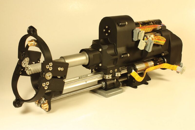
Designing Curiosity’s Actuator Electronics
According to the technical article, “Engineering Systems for Extreme Environments,” by Guy V. Clatterbaugh, Bruce R. Trethewey Jr., Jack C. Roberts, Sharon X. Ling, and Mohammad M. Dehghani, most of whom are members of The Johns Hopkins University Applied Physics Laboratory (APL), “Extreme environments in general can typically be categorized as involving abnormally high or excessive exposure to cold, heat, pressure, vacuum, voltage, corrosive chemicals, particle and electromagnetic radiation, vibration, shock, moisture, contamination, or dust, or extreme fluctuations in operating temperature range.” The authors point out that “These situations are made more extreme when, upon deployment, the system is no longer available for maintenance or repair.”
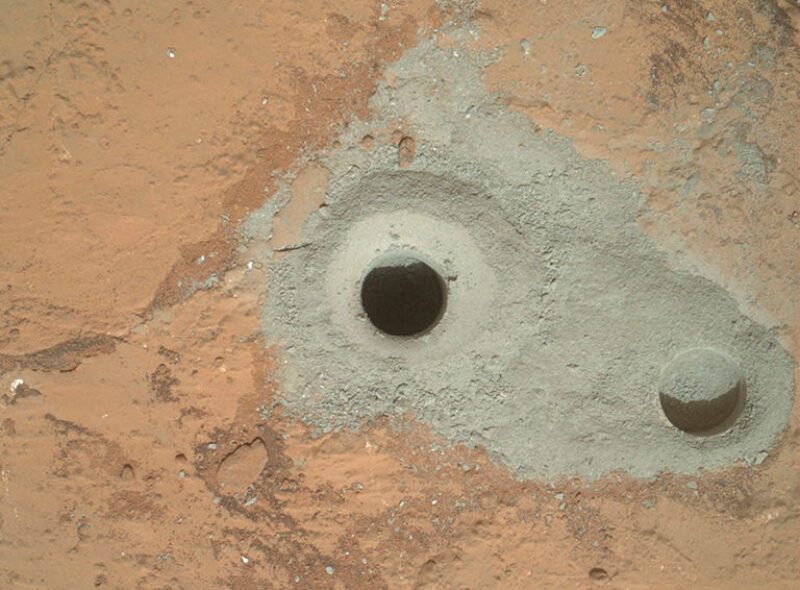
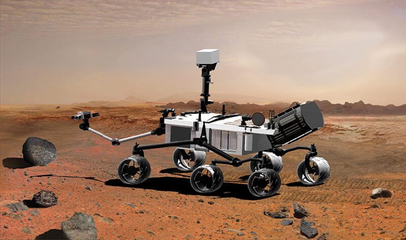
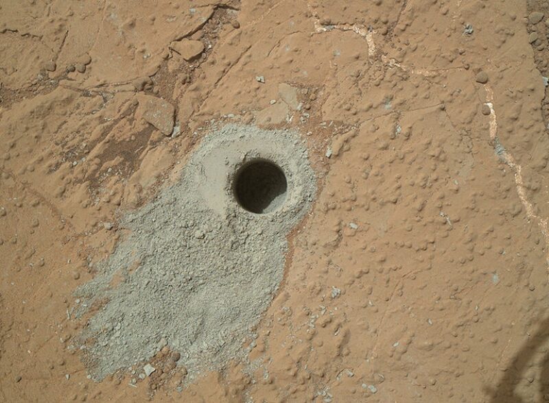
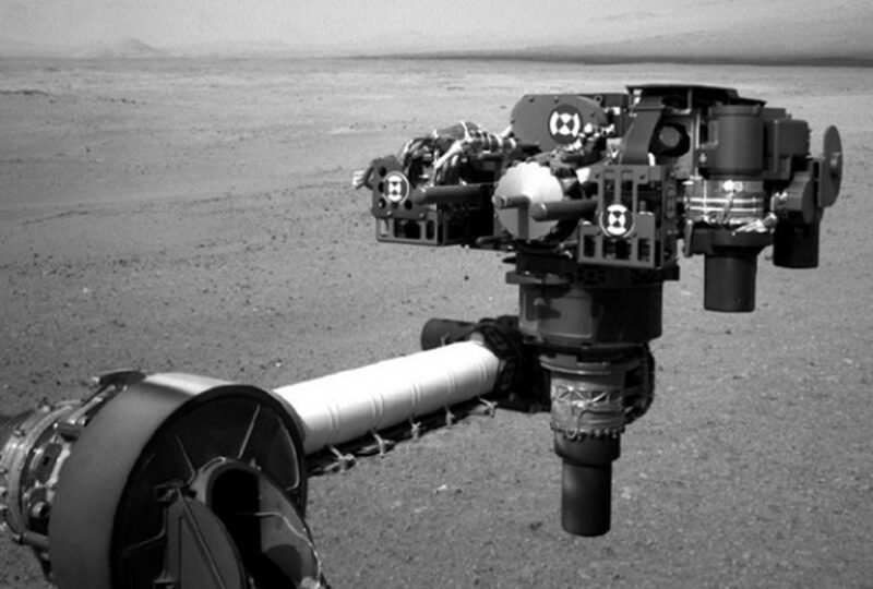
The article, which appeared in Johns Hopkins APL Technical Digest, Volume 29, Number 4, details the approach used in material characterization and environmental testing of the US National Aeronautics and Space Administration (NASA) Jet Propulsion Laboratory (JPL) Mars Science Laboratory Curiosity rover actuator electronics. This is the very same electronics system used to actuate Curiosity’s robotic arm, the part of the rover responsible for completing two exploratory drilling milestones from the Martian surface this year, one on 8 February (a borehole named “John Klein”) and the other on 19 May (a borehole named “Cumberland”).
The careful, detailed approach APL used may help inform analogous characterization and testing efforts in the oil and gas industry.
Mars is indeed an extreme environment “where there is little a priori knowledge about how the system will function.” To obviate failures occurring on the expensive Curiosity mission, the authors discuss important testing and simulation that took place to mitigate system risk, assure system performance, and improve system reliability. “For programs operating in extreme environments, identifying and being prepared to address risk at the earliest stages of concept development is imperative,” the authors state.
One of JPL’s main reliability concerns involved the chip-on-board assemblies (i.e., printed wiring boards with integrated circuits that have been removed from their plastic “packages”). Curiosity was designed with a heated compartment to protect its computer and most of the electronics from the extremes of Martian temperatures. However, the electronics that actuate the motors on the arm and wheels are located far from the heated body and must operate at temperatures that fluctuate from –127°C to +30°C, the maximum daily temperature range on Mars. They are thus more susceptible to failure than Curiosity’s protected computer.
The article asserts that JPL sought APL’s assistance in material characterization and environmental testing. APL says, “One pitfall to be aware of when designing the system is to watch for a critical element on which the entire design may depend. If this element poses some risk, the fallback position would necessitate an entire redesign.”
For example, say the authors, “quite often in electronic packaging of spacecraft electronics, the choice of a connector will determine the arrangement of boards in a chassis, the size of the boards, and even the chassis configuration itself. If the connector proves to be unreliable and there is no equivalent fallback connector, the entire chassis and the electronic subassemblies would have to be redesigned and possibly remanufactured. Such design dependencies or ‘linchpins’ should be avoided if possible to reduce system risk.”
The Physics-of-Failure Method
APL opted to use what is termed the physics-of-failure method, which is a science-based approach that uses modeling and simulation to design in reliability. The method, if not already in use, might prove valuable to the development of materials and electronics for use in extreme oil and gas environments. This approach, say the authors, “models the root causes of failure, such as fatigue, fracture, wear, radiation, or corrosion.” They cite computer-aided design (CAD) tools that have been developed to address various failure mechanisms.
According to the authors, the physics-of-failure approach involves the following:
- Identifying potential failure mechanisms (chemical, electrical, physical, mechanical, structural, or thermal process leading to failure), failure sites, and failure modes
- Identifying the appropriate failure models and their input parameters, including those associated with material characteristics, damage properties, manufacturing flaws and defects, and environmental and operating loads
- Determining the variability for each design parameter when possible
- Computing the effective reliability function (e.g., Weibull function) (Note that a significant amount of testing is typically required for computing such a reliability function, and in many cases a simpler “go/no-go” test may be preferred. However, many existing reliability functions for electronic systems are available in the literature.)
- Accepting the design, if the estimated time-dependent reliability function meets or exceeds the required value over the required time period
The authors state further, “The most common simulation techniques for physics-of-failure modeling in electronic systems include finite element calculation of temperature, stresses/strains, random shock, vibration, buckling, thermal stress, creep, fatigue, mass transport, and electromechanical reaction rates. Statistical methods using Monte Carlo simulations and Arrhenius-based models are also commonly used.”
APL’s desire to use a physics-of-failure approach to addressing the extreme environment on Mars led to a further collaboration with the University of Maryland’s Center for Advanced Life Cycle Engineering.
Before APL designed the temperature cycling testing plan, all potential failure sites were identified using the physics-of-failure methodology:
- Substrate fracture
- Substrate bond pad lifting
- Wire breakage, wire thinning, and ball shear
- Adhesive failure at the die/substrate interface
- Encapsulation cracking
Temperature Cycling Testing, Life Test, and Material Characterization
The APL’s testing and characterization efforts also could find application in developing electronics used in extreme oil and gas environments.
The temperature cycling testing was carefully designed to properly test all the critical failure points.
Three failure modes were observed after extensively testing various materials and careful inspection, using X-ray tomography, of the effects of the testing. All failures were either wire failures or substrate pad lifting failures. Based on the testing and inspection outcome, a combination of the polyimide substrate, an 84-1 die attach adhesive, and a 4402 “glob top” was selected.
Additional “test coupons” were constructed and subjected to a life test performed for a period of more than a year, with a daily temperature cycle between –125°C and +80°C without a failure. The authors state, “Performing an environmental test without using an acceleration factor is a bit unorthodox, but the lack of sufficient existing reliability data over this extended temperature range and the cost associated with failure made the duration of this test a prudent measure.”
APL then carried out a material characterization study to measure the coefficient of thermal expansion (CTE), Young’s modulus, and yield strength as a function of temperature for a variety of materials. Four testing methods were used:
- The dynamic mechanical analysis technique (DMA)—The DMA testing method is particularly well suited to flexible materials such as silicone glob-top encapsulants and the flexible conductive die-attach adhesives.
- Uniaxial tensile testing apparatus—This is used for obtaining yield strength for the rigid epoxies and encapsulants.
- The interferometric strain/displacement gage method—This was assembled at APL for measuring millimeter- and micrometer-scale materials in cases where bulk properties were not valid.
- A flat-plate dilatometer—This was used to measure the CTE of candidate materials as a function of temperature.
The next step was to create an optimized wire bond analytical model. APL personnel attempted to optimize the shape of a wire bond by minimizing its strain energy. “We used the principle that the lower the initial strain energy, the more likely it is that the wire board can sustain deformations without a loss in structural integrity,” the authors state. “The approach taken here was to develop an optimized wire bond shape that was the least susceptible to strains caused by deflections in the glob-top material.”
The finite element method (FEM), which facilitates the use of nonlinear, time-dependent, and temperature-dependent analysis methods, was used by APL personnel to analyze an encapsulated 2-mil gold wire bond for theCuriosity rover actuator electronics. According to the authors, “The nonlinear FEM was a one-quarter symmetric model and simulated the stresses resulting from a wire‑bonded chip cooled from the cure temperature (150°C) down to –125°C. A coupled thermomechanical finite element analysis with temperature-dependent material properties was used. The analysis confirmed that the glob‑top encapsulant chosen for the actuator electronics would not produce an overstressed condition in the assembly, confirming the results of the cycling tests.”
APL cited good correlation between the testing and evaluation (T&E) and the modeling and simulation (M&S) results. The authors state, “It is important to emphasize the link between T&E and M&S. We stated previously that M&S results should guide testing, but the reverse is also true: Good test data should be used to refine models and simulations. This is often an iterative process requiring several M&S and T&E cycles to refine system models.”
Because the Curiosity actuator electronics program produced such good results, the authors are hopeful that long periods of expensive testing can be replaced with relatively inexpensive short-duration simulations for future Martian missions.
Curiosity’s Actuated Drilling Arm in Action
Curiosity was launched from Cape Canaveral 26 November 2011 aboard the Mars Science Laboratory spacecraft. Following the 563,000,000-km journey and after a rather torturous descent (dubbed the “7 minutes of terror”), Curiosity, divested of the spacecraft, landed safely on Aeolis Palus in Gale Crater on Mars on 6 August 2012.
On 6 February 2013, Curiosity’s actuated arm-mounted percussive drill hammered a borehole, dubbed “John Klein,” 6.4 centimeters deep into a Martian outcrop. “This is the first time any robot, fixed or mobile, has drilled into a rock to collect a sample on Mars,” Louise Jandura, sample system chief engineer for Curiosity at NASA’s JPL in Pasadena, California, told reporters.
However, extraterrestrial drilling has also taken place on the moon. Those cores are the only ones returned to Earth, collected by US Apollo mission astronauts (late 1960s and early 1970s) and Soviet Luna program robotic spacecraft (early to mid-1970s) on the lunar surface. The moon, of course, is much closer to Earth than the planets, at a distance of (only) 384,400 km. Mars is a little less than 1,500 times farther away. But, unlike the moon, Mars may have been capable of supporting life.
By the time Curiosity conducted its second drilling operation, 19 May, named “Cumberland,” the results of the first drilling revealed that ancient Mars was likely capable of supporting microbial life—groundbreaking if it is corroborated. According to NASA officials, “The science team expects to use analysis of material from Cumberland to check findings from John Klein.”
Extraterrestrial Drilling Constraints
Missions like the Curiosity stretch the bounds of drilling in an extreme environment, yet at the same time present many constraints that limit their operation. A number of these are noted in SPE 111126, “Drill Automation for the Space Environment: Lessons Learned,” by K. Zacny and G. Paulsen, Honeybee Robotics, and G. Cooper, University of California at Berkeley. In addition to simply surviving the journey from Earth’s surface to the surface of an extraterrestrial destination, the following parameters also must be observed in order to accomplish drilling in outer space:
Electric Power—Curiosity has a radioisotope thermoelectric generator. Heat given off by the decay of an isotope, in this case Curiosity’s 4.8-kg of plutonium-238 dioxide, is converted into electricity by thermocouples. The power source generates 2.5 kWh each day. Waste heat is used via pipes to warm systems, freeing electrical power to operate the vehicle and its instruments. Two rechargeable lithium-ion batteries are charged from the generator, which enables the power subsystem to meet Curiosity’s peak power demands when demand exceeds the generator’s steady output level. Each battery’s capacity is about 42 amp-hours. The rover’s average traveling speed is about 30 meters/hr.
In oil and gas drilling on Earth, a typical rig generator set has a nameplate rating of about 1,100 kW, with larger (around 3,500 kW) and smaller (around 550 kW) units available.
Mass—The maximum weight-on-bit (WOB) that can be applied to the drill is limited by the mass of the rover multiplied by the acceleration due to gravity. The case given in the paper is for an 850-kg rover (Curiosity is actually 899 kg), where the maximum WOB may not exceed 850 kg * 3.68 m/s2=3,100 Newton (equivalent to 300 kg on Earth). This assumes the drill is placed along the rover’s center of gravity. In Curiosity’s case, the drill is deployed from the robotic arm, making allowable WOB much lower.
The mass is constrained by several factors, including cost of the launch, the size of the launch vehicle, and landing technologies for extraterrestrial bodes (landing on the moon is easier than on Mars, because of the lower lunar gravity).
WOB during drilling into the Earth can reach 30,000 to 50,000 lbf. On Earth, mass of the drilling rig is constrained more by its purpose than anything else, with widely different sizes and types of rigs used in a range of operations, including oil and gas well drilling, mining, water well drilling, making subsurface installations, mineral-deposit sampling, or testing rock, soil, or groundwater physical properties.
Temperature, Thermal Fluctuations, Atmosphere, and Pressure—These parameters place physical constraints on the design of all materials and mechanisms, whether used in oil and gas drilling anywhere within the Earth or in extraterrestrial drilling.
Mars: The maximum daily temperature range on Mars fluctuates from –127°C to +30°. Mars’ atmospheric pressure averages about 0.087 psi, about 0.6% of Earth’s mean sea level pressure of 14.69 psi (equivalent to 120,000 ft above Earth’s surface). Mars’ atmospheric mass is about 25 teratonnes, compared to Earth’s 5,148 teratonnes, and it consists of carbon dioxide (95%), nitrogen (3%), argon (1.6%), and traces of other gases.
Earth’s Moon: There is no significant atmosphere on the moon, so it cannot trap heat or insulate the surface. Daytime on one side of the moon lasts about 13½ Earth days, followed by 13½ nights of darkness. When sunlight hits the moon’s surface, the temperature can reach 123°C. The moon’s dark side can have temperatures dipping to –153°C. The Lunar Reconnaissance Orbiter, a NASA robotic spacecraft launched mid-2009 and currently orbiting the moon, measured temperatures of –238°C in craters on the moon’s south pole and –247°C in a crater on its north pole.
Venus: The surface temperature of Venus is about 480°C and its atmospheric pressure is about 900 Newtons per square centimeter (1,300 lb/in.2). Its atmosphere consists of about 95% carbon dioxide, with the remainder mostly nitrogen. A thick layer of clouds is thought to be largely composed of sulfuric acid droplets. None of the several Russian spacecraft of the Venera series lasted more than an hour on the planet’s surface. Earlier Venera probes parachuted into the Venus atmosphere and were crushed by it before reaching the surface. Although the European Space Agency’s Venus Express spacecraft, launched in November 2005 and arriving within Venus orbit in April 2006, has supplied images and data from its orbit, no mission since Venera has attempted to land on the planet’s surface.
Venus Drill—Temperature and Pressure: A Venus drill is discussed in chapter 6, “Extraterrestrial Drilling and Excavation,” in the book, Drilling in Extreme Environments, edited by Yoseph Bar-Cohen and Kris Zacny (Wiley-VCH, 2009). “The benefit of high-temperature motors is that they can drive a sampling drill or a grinder, robotic arm, or a deployment stage on the surface of Venus and thus allow for sample acquisition, transfer, and analysis.”
The authors note that “high temperature is a much more problematic issue to deal with than high pressure. [A] high-temperature application either requires components to withstand this temperature or necessitates some kind of an active (or passive, depending on the time of exposure) cooling system. [An] active cooling system is very expensive and many proposed sample return missions from, for example, asteroids, which had to keep samples cool, could not fit within the mission cost cap. On the other hand, a solution to [the] high-pressure problem can be solved by a pressure vessel, which is a passive system (does not require any power to work).”
Fluids—Temperature and Pressure: According to SPE 111126, “In terrestrial oil well drilling, cuttings removal is often done by circulating a fluid such as water, a mud slurry, or air. In most extraterrestrial setting (moon, Mars, and asteroids), the use of a fluid is not the first choice because of low pressure and/or low temperature conditions. At these conditions, a fluid either freezes or sublimes directly to vapor. Note also that even if a low freezing point fluid were available, the launch cost in excess of USD 20,000/kg would make sending drilling fluid prohibitively expensive. For this reason, most extraterrestrial drills use an auger with helical fluting to convey cuttings to the surface. This makes the drilling process more inefficient.”
Communications Delay—“Of all the constraints, the delay in communication is probably the single most important factor that determines the level of autonomy” in drilling on planets like Mars, states SPE 111126.
Curiosity is equipped with an X band transmitter and receiver that can communicate directly with Earth (at speeds up to 32 KB/sec) and a UHF Electra-Lite software-defined radio for communicating with Mars orbiters. The orbiters have more power and larger antennas, allowing for faster transmission, and thus are relied on as Curiosity’s main means of communicating. The Mars Reconnaissance Orbiter and Odyssey orbiter can communicate with Curiosity for about 8 minutes/day, with data transfer rates that can reach 2 MB/sec and 256 KB/sec, respectively. An average of 14 mins, 6 secs is required for signals to travel one way between Mars and Earth. Information from Earth to Curiosity has to follow the same path in reverse, with the same time delay and window of opportunity constraints.
This constraint alone dictates the need for fully autonomous robotic operation throughout most of an extraterrestrial drilling operation beyond the moon. This is quite different from the concept of automated drilling on Earth. As chapter 6 in Drilling in Extreme Environments states, “In the commercial realm, ‘automation’ and ‘remote control’ mean the capability to watch values and open and close valves with a mouse click in a control room, as opposed to sending out a human with a wrench—eliminating direct hand contact other than joysticks and touchscreens. In space, these definitions imply minimal or no direct human involvement, even with regard to monitoring and decision-making.”
There was no real-time monitoring of Curiosity’s drilling operations but computer command sequences were altered based on the drilling campaign at John Klein. On 5 June, the JPL reported that, “For the drill campaign at Cumberland, steps that each took a day or more at John Klein could be combined into a single day’s sequence of commands. ‘We used the experience and lessons from our first drilling campaign, as well as new cached sample capabilities, to do the second drill campaign far more efficiently,’ said sampling activity lead Joe Melko of JPL. ‘In addition, we increased use of the rover’s autonomous self-protection. This allowed more activities to be strung together before the ground team had to check in on the rover.’”
Lecture Series and Workshop Spark Dialog
Dr. Alfred Eustes, a professor within the Petroleum Engineering Department at the Colorado School of Mines, was selected as an SPE Distinguished Lecturer for the 2013–14 program. His lecture topic is “Extraterrestrial Drilling: How on Earth Can Martian Drilling Help Us?” Eustes is convinced that “What we learn from building and deploying extraterrestrial drilling technology will help us understand how to drill better here on Earth.”
“For example,” he continued, “think of the development of autonomous drill systems for Martian deployment and how applicable those techniques could be here. How about the development of sensor technology for detecting life, assumed to be carbon based just as hydrocarbons are here on Earth? Could those be used here to find oil? And what of material development and machine design for those extreme environments? The X-15 research aircraft was an extreme machine for an extreme environment. And it paved the way for the routine jetliners we use today.”
In further pursuit of dialog between the oil and gas and space communities, a workshop on Planetary Drilling and Sample Acquisition was held 6–8 May at the NASA Goddard Space Flight Center in Greenbelt, Maryland. Several members of the oil and gas-related community participated, from companies such as Halliburton, Baker Hughes, Atlas Copco, and National Oilwell Varco, as well as from universities, NASA, and other companies such as Honeybee, QMI, and ATK (Alliant Techsystems).
Workshop co-organizer, Dr. Michael New, astrobiology discipline scientist at the Planetary Science Division, NASA, said, “The drill used on Curiosity is the best we have. But we want to go deeper. Because, for example, the Mars surface is bathed in ultraviolet radiation, everything gets chemically modified.”
He explained that the Curiosity arm is equipped with a brush that sweeps away the superficial layer of Martian red dust. “A meter or 2 will get you below most of the radiation damage,” he said. “If you want to go deeper—10s or 100s of meters—this is in the realm of a multisegmented drillstring, with borehole stabilization (casing) required. This is really not possible in space at this time.”
New said he has been hampered as the manager of an instrument development program. He receives many proposals for sample acquisition devices such as drills and corers, but wanted focused, strategic guidance on which applications—and therefore technologies—are highest priority. Participants in the workshop helped develop scenarios of the timeframe and feasibility of drilling on extraterrestrial bodies such as comets, Earth’s moon, Venus, Enceladus, and Europa.
As an example, the European Space Agency’s Rosetta is the first mission (currently in “hibernation” until January 2014 on its way to rendezvous with the comet 67P/Churyumov-Gerasimenko) designed to orbit and land on a comet. According to New, it has a small drill on it. “The problem,” he explained, “is that a comet has almost no gravity, so there’s the necessity to bolt down a drill. Then there’s the problem of no weight-on-bit.”
New cited the tension between the constraints of drilling on an extraterrestrial body and the drive to push the frontiers of knowledge. In a short paper he coauthored with Dr. Brian Glass from NASA’s Ames Research Center, “Drill and Sample Acquisition Testing Using Planetary Analogs,” the results of the workshop were discussed: “Future missions requiring subsurface samples will require lightweight, low-mass planetary drilling and sample handling. As discussed in the workshop, unlike terrestrial drills, these future exploration drills will likely work dry (without drilling muds or lubricants), blind (no prior local or regional seismic or other surveys), and weak (very low downward force or weight-on-bit, especially on small bodies, and perhaps 100W of power available).”
- The paper talks about the merits of using drilling analog sites (such as Arctic and Antarctic permafrost, desert, and basaltic sites) here on Earth:
- They provide a relevant environment for testing technical maturity, and for pushing prototypes and beta versions harder, more unpredictably, and with higher overall fidelity than in laboratory bench tests.
- They tend to flush out buried assumptions about durability, connectors, vibrations, and component failure rates at far less expense than on-orbit tests.
- They are valuable for testing and developing new operations concepts. For example, given their natural strata and outcrops, analog sites give a more widely varied set of inputs for drill automation training than laboratory bench tests.
The Future: Mars 2020 and Beyond
On 1 July, a 154-page report was issued that had been prepared by the Mars 2020 Science Definition Team (SDT), appointed by NASA in January to outline scientific objectives for the mission. The mission will send another rover to Mars, which should look for signs of past life, collect samples for possible future return to Earth, and demonstrate technology for advancing toward human missions to the Red Planet.
“The Mars 2020 mission concept does not presume that life ever existed on Mars,” said Jack Mustard, chairman of the Science Definition Team and a professor of the geological sciences at Brown University in Providence, Rhode Island. “However, given the recent Curiosity findings, past Martian life seems possible, and we should begin the difficult endeavor of seeking the signs of life. No matter what we learn, we would make significant progress in understanding the circumstances of early life existing on Earth and the possibilities of extraterrestrial life.”
Drilling again will be a challenge. A drilling device will be crucial for the sampling system. The report states, “[T]he 2020 mission must have the capability to acquire a core from rock/outcrop. The ability to acquire a regolith [extraterrestrial unconsolidated solid material covering a planet’s bedrock] sample would be highly desirable.”
SDT’s Finding 6-1 defines the Mars 2020 mission drilling depth parameter: “The minimum threshold depth for coring into rock is 50 mm. The baseline depth for sampling into rock is >50 mm. Sampling strategies (e.g., fresh ‘bedrock’ exposed by impact) may provide opportunity to sample ‘deeper’ than 50 mm where organic material may be preserved from ionizing radiation.”
The importance of drilling and coring to this mission cannot be overstated—and the oil and gas industry has the opportunity to provide insight and analogs into drill development as well as coring operation design. Samples collected and analyzed by the rover will be essential in helping inform future human exploration missions to Mars. As laid out in a speech delivered 15 April 2010, US President Obama provided a blueprint that includes a manned trip to Mars orbit and back in the 2030s. “A landing on Mars will follow,” he said. “And I expect to be around to see it.”