
To complement managed-pressure-drilling systems, the possibility of introducing new safety barriers directly into the well has been considered. Among these barriers, a new casing valve (CV) with surface control lines, rated for high-pressure/high-temperature and sour environments, has been developed. This paper describes the first application of the 10¾-in. CV in a deep-well sour environment.
Background
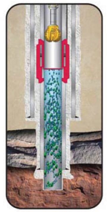
In 2011, a new 10¾-in. 97.1-lbm/ft CV was installed successfully in a well at a measured depth (MD) of 3675 m and a 50° inclination in a hydrogen sulfide (H2S) environment of up to 18%. The well profile was implemented with an S-shaped trajectory featuring a pseudocatenary approach. The CV was set as a permanent installation in 10¾-in. production casing approximately 400 m inside the preceding 13⅜-in.-casing shoe (Fig. 1). CV position details are as follows:
- CV setting depth: 3675-m MD [2899-m total vertical depth (TVD)]
- 13⅜-in.-casing shoe: 4075-m MD (3155-m TVD)
- 10¾-in.-casing shoe: 4947-m MD (3837-m TVD)
CV Construction and Operation
The CV is a full-bore and surface-controllable flapper-type valve that can be installed as an integral part of a casing string and can serve as an additional downhole barrier to seal the wellbore pressure/fluid below it. A CV can be used to avoid the need for snubbing operations, or the need to kill the well in order to trip the drillstring and install completion assemblies during near-balanced and underbalanced operations. It represents an additional downhole mechanical barrier because it can be inflow tested, for instance with a lubricator valve installed with the casing. The valve surface control is achieved by a two-way armored control line that runs from the valve to the surface control panel and hydraulic-power unit. To open the valve, pressure is applied one way, and to close the valve, it is applied the other way. The presence of the control lines requires modification and penetration of wellheads.
The design of the CV allows the passage of the bottomhole assembly (BHA) and all downhole equipment when in the open position. When tripping out of the hole, the string is tripped out until the bit is above the CV, which is then closed and the casing annulus pressure above the CV is eventually bled off. The drillstring can then be tripped out of the well without the use of a snubbing unit and at conventional tripping speeds, thus reducing rig-time requirements and providing improved personnel safety.
The CV can also be used to trip in the hole. The drillstring is tripped back into the well until the bit is immediately above the CV; the annulus pressure can be equalized, the CV is opened, and the drillstring is run in to continue drilling operations.
Closed-Hole Circulating Drilling (CHCD) Mode
CHCD is a managed-pressure-drilling technique used when drilling presents the risk of severe losses in highly fractured formations. CVs are particularly helpful, and highly increase operation safety, in CHCD mode. Usually, in CHCD mode, the annulus is kept full of light annular mud (LAM), which is slightly in underbalanced condition with respect to the pore pressure at the top of the fractured formation. In order to restore the surface pressure balance, the annulus between the well and the drillstring is kept closed by a rotating control device (RCD) or a rotating blowout preventer, which is sealed with a rubber element around the drillpipe (DP) and constitutes a barrier during drilling.
Before starting to trip out, a sacrificial fluid inside the BHA is displaced by kill mud (with specific gravity higher than pore pressure) and all the annulus is displaced with new LAM in order to have a homogeneous fluid specific gravity for better control of the tripping process. This is a requirement especially for highly inclined wells, where the possible slippage of gas/oil on the high side of the well can be facilitated. During the tripping process, the annulus pressure is constantly monitored to detect any influx/losses. Once this happens, kill mud or base oil is pumped through the annulus, depending on whether influx or losses are detected. The most risky situation while operating in CHCD is the tripping in/out of the heavy BHA. Because of the specific dimensions of the BHA, sealing by the RCD is not possible because the RCD is temporarily laid down in order to allow the passage of the heavy BHA.
The well is maintained in a slightly controlled-loss condition by pumping kill mud into the annulus, while the mud level is constantly monitored during the time required to pull the heavy BHA out of the hole or to run it in the hole. During the tripping of the heavy BHA, the only well barrier present for the annulus is the kill mud. The planning of materials/chemicals and good logistics management, together with the preparation/skills/training of the personnel, are therefore the key points for guaranteeing the success of the CHCD technique.
The CV application allows isolation of the wellbore once the entire drillstring is above the valve. In fact, in this condition, the CV can be closed and inflow tested. The tripping procedure can then be carried out as per conventional-drilling mode. In particular, in the case of long-duration trips and in the presence of a narrow window between the pore pressure and the fracture gradient and in CHCD mode, the operating rig time can be reduced considerably and the necessity to kill the entire well with a kill mud can be fully prevented when the BHA is tripped.
It can, therefore, be concluded that the availability of a CV is of paramount importance in reducing rig-crew stress, blowout risk, and environmental impact.
CV Specifications
The new 10¾-in. CV was designed to meet the following technical specifications:
- 8¾-in. nominal internal diameter; 12-in. nominal outer diameter
- Collapse pressure of 11,900 psi (82 MPa)
- Burst pressure of 11,400 psi (78.6 MPa)
- Tensile strength of 1.700.000 lbf
- Flapper differential pressure of 200 psi minimum, 5000 psi maximum
- Resistant to H2S concentrations up to 18%
- Resistant to CO2 concentrations up to 6%
Results
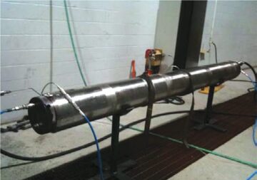
Before drilling applications, the CV was tested (Fig. 2) and a risk analysis was performed. The risk assessment showed an overall blowout probability reduction of almost one order of magnitude compared with a 1% well-integrity--failure increase caused by the CV’s introduction. This result indicates that CV application to critical wells and during CHCD operation is highly beneficial. In addition, well-integrity issues can be mitigated further by setting a scab liner as prevention during well operations, or remedial action (through a workover campaign during well production).
The benefits of the CV during well operations have been identified and quantified statistically, considering as a baseline the probability of blowout derived from an internal study developed in 2008 on CHCD mode. The risk of blowout in CHCD was then calculated to be reduced by 75% because of the CV implementation, which greatly improves the weakest blowout path.
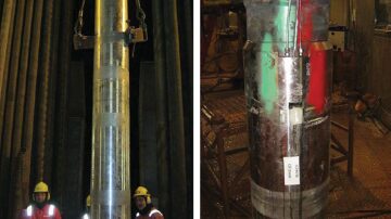
The installation of the CV in an operative well was achieved with success, with the CV set at a depth of 3675 m at a 50° inclination (Fig. 3). The well has a potential sour environment of up to 18%. The installation was performed following CV-operations-manual procedures. Although there were issues with fluids circulation caused by the limited annular clearance between the 13⅜‑in. casing and the control-line protectors (CLPs), the casing string was run to bottom and the casing hanger was landed successfully, thus avoiding the requirement of using the wellhead-tee-penetration contingency method for the control lines. The CV wellhead penetration was performed, and the CV was function tested successfully and flushed with clean oil-based mud.
A set of function tests was carried out on surface before running in hole. Checks were made to confirm that the CV connection-protector clamp was fitted correctly to the CV and that the CLP was fitted to the casing. A concern was raised with the planned running of several casing joints with offset centralizers immediately below the casing hanger. Although the offset centralizers would allow a passage for the control line, it was decided there was a possible risk of damaging the control line, so the decision was made to use standard joints instead of the casing joints with centralizers. Another concern was raised about the length of time the string would be static during the hanger termination (30 minutes) and the time required to function test the CV (45 minutes), and the decision was made to perform the function test at one joint before installing the hanger joint, to reduce static time and the risk of being stuck in hole.
The control-line sheave was hung from the static line that the rig had in place for wireline sheaves, and a sling was installed from the sheave to the mast as a safety line and to hold back the sheave so that it would not interfere with the travel of the topdrive. The control-line spooler was placed on the rig floor, and the spooler unit was made ready for connection to the CV. The CV was lifted to the rig floor and brought up to the casing with no gripping of the CV. The control lines were connected, pressure tested, and protector fitted. The CV was run through slips and, once in the wellbore, was brought to the closed position and back to the open position. The CV was then run in hole with a CLP fitted at every joint.
The CV was run to one joint before the bottom, where the valve was functioned in the closed and open positions. The final joint was made up, the hanger terminations were carried out, and the hanger was landed successfully.
The cementation was followed by flushing of the CV while reciprocating the string and pumping from 3885 to 3665 m, a process that was repeated three times and followed by a final function test of the CV. Once the function tests were complete, the DP was run back in hole to 3885 m and circulated for approximately 1 hour, then pulled out of hole once the drillstring cleared the CV. A pressure of 500 psi was applied to the open line and 200 psi was applied to the closed line of the CV. This was confirmed with the gauges at the wellhead while the pressure was isolated on the control lines at the wellhead. The surface control unit was removed because the well was suspended temporarily until drilling of the 8½-in. section of the well could be performed.
This article, written by JPT Technology Editor Chris Carpenter, contains highlights of paper IPTC 16936, “New 10¾-in. High-Pressure/High-Temperature Casing Valve Successfully Applied in a Deep-Well Sour Environment,” by Paolo Ferrara and Claudio Molaschi, Eni E&P; Bill Menard, Weatherford; and Francesca Rinaldi, Eni E&P, prepared for the 2013 International Petroleum Technology Conference, Beijing, 26–28 March. The paper has not been peer reviewed. Copyright 2013 International Petroleum Technology Conference. Reproduced by permission.