The surface-controlled subsurface safety valve (SC-SSSV) is an integral part of the overall safety system of any well, and it is the only method that provides subsurface isolation in case of emergency caused by uncontrolled surface or subsurface events. The effectiveness of these valves can be threatened by leaks, plugs, or breaks in the control lines (CLs). This paper describes a methodology that deploys CLs on the inside of the tubing, reducing cost and ensuring continued effectiveness of SC-SSSVs.
Introduction
Functional SC-SSSVs must be installed in production tubing in all gas and oil wells, irrespective of location, as a safety barrier to halt flow in case of a catastrophic failure. SC-SSSVs are held in the open position by introducing hydraulic positive pressure from the surface. This pressure is applied through a CL in the tubing/casing annulus running from the valve to the surface. In case of an emergency shutdown, the hydraulic pressure will be lost, forcing the safety valve to close.
CLs for SC-SSSVs could leak, plug up, or break, leading to loss of the capability to control the valves’ operating condition, causing environmental and safety concerns in addition to a loss of production upon closure of the valve.
In one of the giant Abu Dhabi onshore oil fields, approximately 160 strings have with damaged-CL problems. In the past, the only way to rectify SC-SSSV problems was to pull out the production tubing through a rig workover. Hence, all affected wells were enrolled in a drilling workover schedule. Rig availability is one of the major challenges affecting field-development plans, and so any rigless technologies that can be used in place of rig workovers are of high importance to save on rig time.
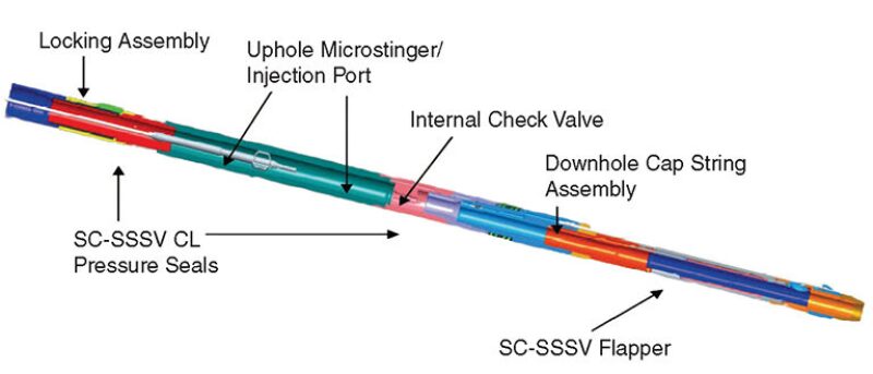
A multidisciplinary team was formed to survey the market and carry out an evaluation of technologies that could remedy the problem of the damaged CL by replacing or modifying the existing SC-SSSV riglessly. The findings of this survey indicated that there were two technologies that could restore the functionality of the SC-SSSV riglessly. One of these is an SC-SSSV with a CL line deployed inside the tubing (Fig. 1). This can be compared with conventional CLs, which are set in the annulus (outside the tubing string) and hence require rig intervention in case of damage. The running and retrieval of this modified SC-SSSV are performed by a conventional slickline unit; however, the CL requires special equipment (a capillary unit) for installation and retrieval.
After careful review and confirmation of the applicability of this system in most of the affected wells, the team proposed trials in one of the major fields to assess the effectiveness of this technology.
Candidate Selection for Trial
The multidisciplinary team investigated all wells with reported SC-SSSV problems in the field to select a suitable candidate for the trial on the basis of proper selection criteria. Site visits were conducted, and the well was selected on the basis of the wellhead configuration, well status (active or inactive), and the nature of the individual SC-SSSV problem. The first well selected, scheduled for a workover because of a blocked CL, was a single oil producer.
Modified SC-SSSV System Requirements
The valve is run into the well using a standard wireline unit. The valve is located inside the existing SC-SSSV and locked into position. Once the valve is locked into position, the wireline running tool is retrieved. The valve has an internal stinger receptacle. The receptacle is used to communicate CL fluid to the valve.
The hydraulic fluid required to control the new SC-SSSV valve will be transferred to the valve through a ¼- or ⅜-in. capillary string. The capillary tubing and stinger used for transferring the CL fluid will be terminated at surface through a hanger system or a modification to the current tubinghead-hanger arrangement. The hanger is installed below the existing production tree.
Wellhead Modification
To install the new system, a wellhead modification is required to transfer the injected hydraulic fluid through the newly installed inner CL. Different options were considered in modifying the wellhead. One was to install an extra adaptor spool; however, this will impact the tree height and consequently will affect the flowline design. Another option is to convert one of the test ports to an injection port. This would require porting the coupling seal. The capillary tubing hanger has seals that would straddle the ported coupling seal, guiding the injected fluid down the capillary string and providing a second barrier to the primary ring-gasket seal.
Risk Assessment
The risk assessment was carried out jointly with field operations and technical engineers and followed ADCO standards and a risk-assessment format that covered the following aspects:
- Equipment preparation
- Well preparation, including killing of the well, wellhead modification, pressure test, CL hanger, and unloading the well
- SC-SSSV system installation, including rigging up and running/pulling procedures (capillary string and stinger assembly)
- System functional testing, including testing in accordance with American Petroleum Institute Recommended Practice 14B standards
The assessment identified potential hazards and consequences along with the control measures in place. The residual risk was low, allowing the acceptance of the overall system functionality.
To ensure that the system will function properly with the modified wellhead per the company standard, a full-day session was conducted to review equipment demonstration and required testing. In addition, a full-equipment hazard-and-operability session was conducted in the company workshop with the involvement of all concerned parties.
Installation Operations
As per the preset plan, the operation was carried out and completed in 3 days (daytime operations only). The first 2 days were dedicated to installation, and the third day was dedicated to testing the system. The most critical part of the operation was the installation of the capillary line, because it required high accuracy in taking measurements and making the final cut to accommodate the line exactly between the downhole valve and the hanger mandrel.
After completing the installation, the whole system was functionally tested twice and then pressure tested to 4,500 psi (static) for 24 hours. Upon confirmation that the system held pressure with no sign of leakage, a dynamic test was performed successfully.
Trial Results
Upon completing all the required tests on the system, it was lined up to the existing well and wellhead-control panel, and the well was flowed back to the production facilities.
Since installation, an intensive program for well-monitoring and system-functionality checks was implemented to evaluate system performance. The results were excellent; the SC-SSSV with the new CL is working and functioning properly.
A schedule for monthly system-functionality tests was established with the service company to ensure the system’s reliability and to report any findings that could assist with future applications.
Potential complications were discussed and investigated by the concerned parties before the execution phase; moreover, a dummy run was carried out in the workshop. Still, there were some challenges faced during the actual installation operations. The team managed to solve those challenges in a timely manner to complete the trial safely and successfully. These points will be discussed and considered in future work.
Recommendations
- As a result of the successful trial of this system, this innovation is currently being practiced in existing wells and will be continued for future development projects because of its safety profile and cost-effectiveness.
- The system overcomes the problem of the damaged CL and malfunction of the SC-SSSV by running a complete SC-SSSV system and new CLs riglessly without involving rig workover action.
- The new SC-SSSV is operated by using the existing wellhead-control panel, without adding any new surface facilities or equipment to the wellhead area.
- This system was installed successfully in one candidate well for the first time in the Middle East. The well is now running safely in line with company policy.
- The system cost is only approximately USD 250,000 compared with the the cost of rig-workover action of USD 1.5 million.
- Such techniques can be applicable in all fields where wells are having SC-SSSV problems such as CL leakage or plugging problems.
This article, written by JPT Technology Editor Chris Carpenter, contains highlights of paper SPE 164370, “Innovative Methodology To Riglessly Restore the Functionality of Subsurface Safety Valves (SC-SSSVs) With Damaged Control Lines,” by Mohamed Fahim, Hossam Elnaggar, Abd Allah ElBarbary, Mohammed Abu Arab, Ashraf Keshka, Hamdi Bouali Daghmouni, and Mohamed Al Karra, ADCO, and Ammar Soufan, Joseph O’Connor, and Magdi Elasmar, Baker Hughes, prepared for the 2013 SPE Middle East Oil and Gas Show and Exhibition, Manama, Bahrain, 10–13 March. The paper has not been peer reviewed.