One notable improvement originating from recent field experience is the novel use of injection-/inflow-control devices (ICDs) in a conventional steam-assisted-gravity-drainage (SAGD) well pair. The use of a properly designed ICD completion has proved beneficial to the processes of developing the steam chamber and improving the inflow profile of the producing well of the SAGD pair. Work conducted in the Surmont field of Alberta, Canada, provided an excellent starting point to optimize flow-control improvements to the SAGD process.
Introduction
To obtain high efficiency, the SAGD process demands a high degree of steam conformance along the wellbore. The better the steam conformance, the greater the amount of oil mobilized and the higher the potential for oil recovery. However, conformance should not come at the cost of excessive steam injection.
A number of thermal inefficiencies (described in the complete paper) are unavoidable in the SAGD process. These collectively result in a deformed and nonoptimal steam chamber that undermines energy maintenance and lowers the ultimate recovery factor. By incorporation of flow-control devices (FCDs) into the injector or producer well, however, a more ideal, more desirable chamber shape can be realized.
Overview of ICD Geometries
Fundamentally, all flow-control devices operate by the same mechanism: They provide an additional pressure drop at select points in the completion string to complement the pressure drop of fluid moving through the reservoir as well as internal pressure drops within the completion itself. Despite this fundamental similarity, however, the methods by which different styles of ICDs create this pressure drop vary strongly with design.
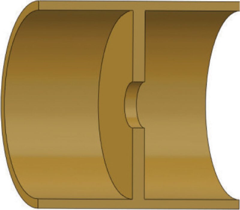
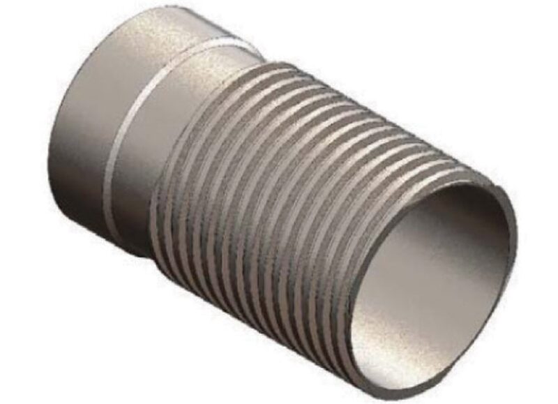
There are three distinctive categories of passive inflow-/injection-control devices (PICDs) available today. The two most common PICD geometries are orifice/tube/nozzle-based (restrictive) (Fig. 1) and helical-channel/-baffled-pathway (frictional) (Fig. 2). The restriction-based PICD uses fluid constriction to generate a differential pressure across the device. This method essentially forces the fluid from a larger area through small-diameter ports, creating flow resistance. A frictional-pathway PICD relies instead on surface friction to generate a similar pressure drop. These designs produce a distributed pressure drop over a relatively long area, as opposed to the instantaneous loss through a restriction-style PICD. When fluid flows through the channel/channels, fluid rheology and channel characteristics interact to create the designed pressure drop.
The third category of PICDs, autonomous PICDs, provides unique functionality. Autonomy, as it relates to an ICD, is defined as the ability of a device to passively adapt to changing downhole conditions in a way that controls unwanted fluids while preferentially producing desired fluids. Frictional- and restriction-style ICDs, while excellent at creating a uniform flow profile, have traditionally been challenged by the fact that, should an undesired fluid break through to the device, the pressure drop across the device would lower for the undesired fluid. This causes an undesired fluid to be produced preferentially over desired oil across the length of the lateral. Autonomous ICDs reverse this performance behavior. This new category of ICDs exhibits the greatest variation in design because multiple methods have been used to achieve a pressure drop that adapts with reservoir and fluid conditions; thus, making categorical statements about all autonomous ICDs is difficult. The authors focus on an autonomous ICD geometry best described as a hybridized design, incorporating elements of both restriction- and frictional-style ICDs.
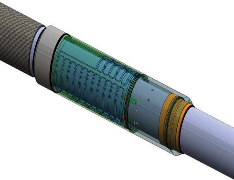
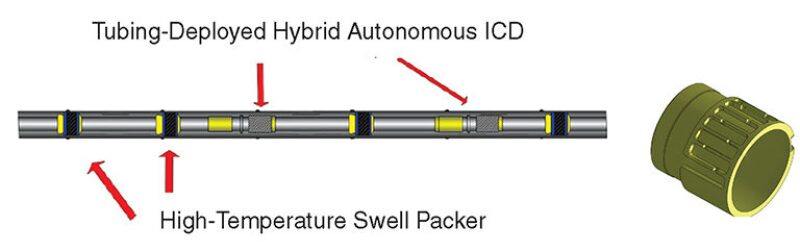
Two variants of the hybrid autonomous ICD exist commercially: a liner-deployed version with the option of an integrated screen component (Fig. 3), and a tubing-deployed system that could be deployed within an existing screen- or slotted-liner-completion hookup (Fig. 4).
Factors Contributing to Steam-Chamber Nonconformity
Choices made during the drilling and completion process, and heterogeneities in both geological and fluid properties in the reservoir, contribute to the variance and nonconformity of the SAGD steam chamber. While drilling the SAGD well pair, small offsets in the horizontal and vertical distance between injector and producer can contribute significantly to the size and development of the SAGD steam chamber, the SAGD peak oil rate, and the ultimate recovery factor. Similarly, decisions about the rate and manner of steam injection can distort the steam-chamber shape. Injected steam is of relatively high quality in SAGD injectors and exhibits traditional gas-flow behavior as it moves down the injector tubing. Under the typical volumetric flow rates observed in the SAGD injector, inertial contributions of steam flow will be large and, as a result, the pressure in the perforated interval may actually be higher at the toe of the well than at the heel if steam is bullheaded down the injector. This is contrary to the traditional liquid-flow case, where viscous forces dominate and the pressure falls along the wellbore from the heel to the toe. Thus, for conventional designs that do not use multiple points of steam injection, high flow rates may create a pressure gradient that favors steam flow into the reservoir disproportionately at the toe of the well. This set of conditions is rarely the case, but it does demonstrate how completion-design choices can skew steam conformance.
Nonconformity of the steam chamber is much more sensitive to heterogeneity in the reservoir, which can originate from a number of different physical properties. Bitumen-bearing oil sands exhibit three typical characteristics: a high-native-viscosity oil, low reservoir temperature, and a high degree of heterogeneity over several length scales. Heterogeneity in the reservoir includes parameters such as porosity, permeability, rock composition, phase saturation, anisotropy, and even oil-phase viscosity, which is shown to vary by several orders of magnitude vertically through the reservoir and up to a factor of five laterally through the reservoir.
The goal thus becomes using FCDs in the injector to counterbalance the distorting features of the well and reservoir itself. If a synthesis of these influences is achieved, steam conformance along the wellbore will be improved, with the result being a greater amount of oil mobilized and a higher potential for oil recovery.
Variations in the Steam Trap
While the focus thus far has been on the injector, and the usefulness of uniform flow profiles to improve steam-chamber conformance, significant additional value can be established by improving the uniformity of the producer flow profile. In the production lateral, uniform production profiles relate to the operational tool known as the “steam trap.” The steam trap refers to an intentional liquid layer maintained above the producer well, kept just below the boiling point of water. It has been observed that when bitumen emulsion and condensed water are removed more slowly than gravity feeds liquid to the producer, a liquid layer builds up over the production lateral and the the tendency of the steam to flow directly to the production well can be reduced or possibly eliminated. This is analogous to the ability of a steam trap to allow the flow of condensate from the bottom of a steam-heated radiator without allowing significant bypassing of steam; unable to displace the higher-density liquid surrounding the producer well, the valuable steam is diverted back into the steam chamber. However, maintaining this steam trap is operationally difficult. In field operations, the height of the steam trap and how it varies along the lateral length cannot be measured directly. Instead, the height of the liquid layer is an estimation based on the temperature difference between the saturation temperature of the injected steam and the temperature at the corresponding point on the producer well, a temperature difference known as the “subcool.” The higher the liquid level above the producer, the lower the temperature at the producer and the higher the value of the subcool. Because real-life reservoirs are invariably heterogeneous, it becomes extremely difficult to achieve a uniform subcool along the entire horizontal length of a well.
Introduction of ICDs mitigates the risk of a nonuniform steam trap along the producer well. With uniform production from all points of the lateral, one can achieve a significantly lower average subcool while remaining certain that steam breakthrough does not occur, because liquid will be present above all points of the lateral to serve as a mechanical diverter to vapor. Operating at lower average subcool values allows maximum surface area to the steam chamber, greater interface contact, greater oil-recovery rates, and no risk of flooding the injector well.
FCD Design Guidelines
Given the numerous factors that contribute to reservoir heterogeneity and nonconformance of the steam chamber, the primary challenge in completion design becomes the task of determining the optimum number of FCDs, their location along the wellbore, their resistance setting, and the desired mass-flow rate through each device. For the injector lateral, the ultimate goal is to create uniform steam distribution such that the steam chamber will grow uniformly along the entire wellbore.
For the producer lateral, the goal is for uniform production of bitumen emulsion and steam condensate in a manner that creates a uniform and reliable steam trap that protects the economic investment in steam generation and protects downhole equipment (artificial-lift pumps in particular) from damage. The optimal design would be one in which the well dynamics offset or cancel nonuniform steam conformance and production arising from reservoir heterogeneity. To establish how resilient a given FCD design is to time-varying reservoir behavior, numerical simulation is necessary.
Certain heuristics are in use to suggest initial FCD design. For example, the pressure drop across an FCD at given operational conditions must be equal to or greater than the pressure drop of the fluid in the reservoir itself. If the FCD fails to provide this minimum pressure drop, a higher-resistance-rating FCD geometry should be used, the number of FCDs should be reduced to increase the mass flow rate across each device, or some combination of those two options should be implemented. Similarly, if the mass flow rate per device exceeds the mechanical limits of the device, then the number of devices contacting the reservoir must be increased to reduce the average flow per device below this mechanical limit.
Determining whether to use a liner-deployed system or a tubing-deployed system is less clear-cut; using a liner-deployed system is advantageous when significant geological data are available during the design phase. This deployment option allows for better sand-control options with greater inflow area and allows for a conforming steam chamber from first steam. However, a tubing-deployed system allows for remediation once actual field data have been collected.
Having established deployment method, number, and average setting for the FCDs, a nonoptimized completion design is then imported into a coupled reservoir simulator with a thermal-modeling engine. For a detailed discussion of the example reservoir model and simulation results that demonstrated that FCDs overcame a number of geological limitations to create a more uniform steam chamber, please see the complete paper.
This article, written by JPT Technology Editor Chris Carpenter, contains highlights of paper SPE 166266, “The Role of Autonomous Flow Control in SAGD Well Design,” by Sudiptya Banerjee, SPE, Robert Jobling, SPE, Tarik Abdelfattah, SPE, and Hang Nguyen, SPE, Baker Hughes, prepared for the 2013 SPE Annual Technical Conference and Exhibition, New Orleans, 30 September–2 October. The paper has not been peer reviewed.