
The Schiehallion floating production, storage, and offloading vessel (FPSO) is moored by a turret-mooring system (TMS) located in a water depth of 400 m in the Atlantic in very challenging environmental conditions. The Schiehallion FPSO went onstream in 1998. As part of the planned field development, the Quad 204 FPSO currently under construction will replace the producing unit in 2015. This paper compares the main features of the Schiehallion and Quad 204 TMSs, reporting the performance of key components over 15 years of operation.
Introduction
A contract was signed in June 1995 between BP and an alliance of partners to develop an FPSO for Schiehallion. Sanction was given to the project by BP and their partners in February 1996.
The harsh environment encountered in the Schiehallion field, offshore the Shetland Islands in the Atlantic Frontier area, required a new dimension of a mooring system. An internal turret was chosen to allow the vessel to freely weathervane and to transfer the fluids and services from subsea to the vessel and vice versa. The required turret diameter to accommodate 24 risers precluded the use of a conventional slewing-ring arrangement, as was used in previously built North Sea turrets.
The new Quad 204 FPSO that will replace the Schiehallion will be a double-hulled vessel 260 m in length designed for harsh weather and continuous operations in the west Shetland area.
BP
Schiehallion
FPSO
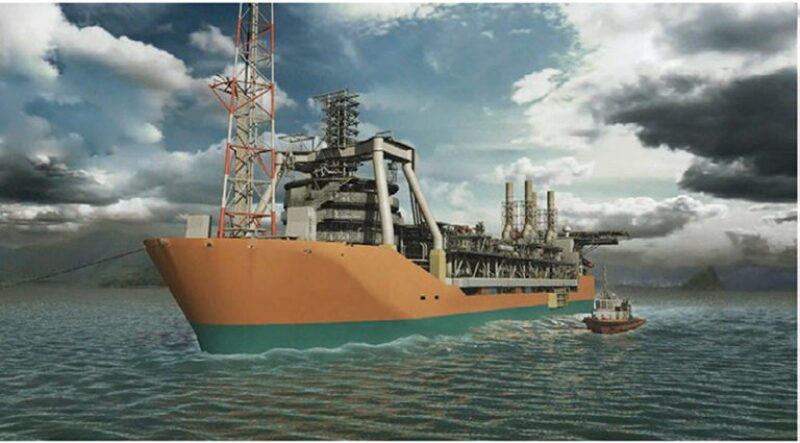
The Schiehallion is at this time the world’s largest purpose-built vessel, capable of storing 950,000 bbl of oil, with a length of 245 m, a width of 45 m, and a depth of 27.25 m (Fig. 1 above). A simple barge-type hull was chosen, incorporating a design life of 25 years in situ, with a fatigue life of 50 years and the capacity to survive the 100-year-storm condition. A high forecastle was designed to protect the forward process area and the turret. Accommodation astern of the vessel provides full temporary refuge facilities for 80 persons.
For stability performance, ballast water tanks are segregated and arranged to form a double-sided hull. Two aft-mounted thrusters are implemented for heading control during offloading operations to tandem-moored shuttle tankers.
Mooring System. The mooring design is based on an entirely passive mooring (i.e., no assistance of a dynamic-positioning system is required for station keeping). The natural FPSO weathervaning capacity ensures minimum environmental loading on the catenary mooring arrangement.
The mooring system was conceived of by analytical methods validated by a series of model tests in a 1:80 scale representing the 400-m water depth at the site.
The criteria for the mooring design were as follows:
- Survival of 100-year-storm condition (intact/one line broken/transient case)
- Four bundles of mooring lines allowing for large corridors for the risers
- Mooring stiffness independent of offset directions
Fourteen anchor legs, bundled in an anchor pattern of 2×3 and 2×4 legs and using a combination of 6¼-in. studless chain (a first) and 146-mm-diameter sheathed spiral-strand steel cables, enable the criteria to be met. Suction anchors placed in a radius of 1650 m provide the required holding capacity.
Top-Mounted Internal Turret (TMIT). The fixed part of the turret is composed of a 14-m-diameter cylinder, inserted through the vessel hull and supported at the vessel’s deck level on the turret collar by a bogie-bearing system (for further details on the bogie-bearing system, please see the complete paper). This system allows the vessel to weathervane around the turret, and comprises a series of 20 vertical bogie assemblies and 18 radial wheels. The vertical bogies and the radial wheels run on bolted and sectored rails. All components can be replaced in situ should the need arise.
Fluid-Transfer System. The FPSO topside facility is designed to handle in excess of 145 million bbl of oil and 140 MMscf/D of gas production. The production scenario comprises five drilling centers, with a total of 16 production wells, 12 water-injection wells, and one gas-disposal well.
The turret provides the link between the earthbound incoming and outgoing flowlines and the topside placed on the weathervaning vessel. In addition to the previously mentioned services, there is a requirement for individual-well testing, well control (hydraulic and electric signals), chemical injection, and gas lift. A large, multipath swivel stack handles the transfer of these lines from within the turret-mounted manifold to the gantry structure placed on the vessel deck or vice versa.
In order to allow for the initially installed 13 flowlines and two umbilicals, and the additional risers planned for the future, the turret contains 24 I-tubes. The flexible risers that transfer the fluids from the seabed to the FPSO enter the turret structure through the bottom and continue to the deck level of the vessel at the top of the turret, where the end fittings are connected to the hard piping. This allows an above-water dry connection of the flexible risers. Bend restrictors protect the riser sections below the chain table (vessel keel level).
Upper-Turret Manifold and Gantry. An open manifold structure houses the shut-down and emergency-shut-down valves, the piping headers and pigging equipment, the turret equipment room, and the chain and riser installation winch.
Three elevated decks, stepped in diameters from 22 to 16 m above the riser deck, are arranged to form a cone with a height of 27 m above the main deck. A three-legged pyramid gantry structure is fitted over the manifold. This structure carries all the piping to the vessel deck and supports a hydraulic turret crane for maintenance and a windshield structure allowing personnel to work protected in the manifold, which is equivalent in size to a 10-story building.
Swivel Stack. The swivel stack is the heart of the TMIT, transferring all fluids and services from the fixed turret to the freely weathervaning vessel. It accommodates a full 360° rotation during full service life. During the design of the Schiehallion TMS, it became apparent that the required swivel stack would become extremely complex and large. Previously produced stacks were mounted atop the manifold, with the external housing driven from the gantry. This “normal” concept resulted in a total height of 36 m from the vessel deck for the top of the turret crane.
A challenge to reduce the overall height resulted in an unusual inverted swivel stack with a number of advantages, including reduction in overall height for the turret top, reduction in gantry height and piping length, and protected access to swivels for inspection and maintenance.
BP Quad 204 FPSO
The vessel will be able to store 1,000,000 bbl of oil, with a length of 270 m, a width of 52 m, and a depth of 27.25 m (Fig. 2).
Mooring System. The FPSO will be turret moored in the same location as the existing vessel through an anchor-leg system composed of four bundles of five legs laid within the same sectors as the present Schiehallion anchor-leg bundles, thereby keeping free the access corridors for the existing risers and umbilicals.
TMIT. At the turret bottom, the risers and umbilicals are routed through tubular guides (I-tubes) to, respectively, a riser support deck and an umbilical connection deck in the upper portion of the turret cylinder. Piping spool -pieces connect the riser termination flanges in the turret to the piping on the decks of the manifold. From the manifold decks, the fluids are routed to the fluid swivel stack.
The chain stoppers are mechanical systems that transfer the mooring load to the lower-turret fixed structure. The chain stoppers are considered to be key technology items because of the resulting mooring-load level and chain-fatigue aspect. In addition, the connector’s offshore changeout is possible without interrupting production.
Bogie-Bearing System. For bogie-system designs after the Schiehallion TMS, the bogie radial-guide wheels fulfill the function of guiding the bogies along the track and replace the former tie rods. Otherwise, the weathervaning-system materials recently used are very similar to those of Schiehallion, the system being scaled to specific requirements.
The axial wheels mounted in each bogie (32-off) counteract the gravity, heave acceleration, mooring lines, and riser loads and moments. The radial wheels (36-off) counteract the horizontal loads caused by vessel motions, wind, current, and waves.
To minimize friction, both the axial and radial wheels run on roller bearings. The wheel/rail interface is greased by an automatic system fixed on the bogie in order to prevent corrosion and to reduce friction and wear.
Fluid-Transfer System. Turret Manifold and Gantry. A multideck super-structure (manifold), located on top of the turret, houses installation and production equipment and piping manifolds, and supports the fluid swivel stack. Access to the fixed part is achieved directly from process deck to collar deck. A gantry structure is positioned above and around the superstructure. The turret design allows for maintenance in operation, which maximizes availability over the full field design life.
Swivel Stack. The swivel-stack assembly includes all individual swivel units, the swivel supports between swivel units, and all internal piping and cabling of the stack. The swivels allow the transfer of fluids, utilities, chemicals, electric power, and electrical and optical signals between the vessel, turret, and seabed equipment.
The fixed portion of each swivel pipe run extends downward from the swivel-inner-shell flange connection to the turret-deck-piping flange connection. The rotating portion of each swivel pipe run extends outward from the swivel-outer-shell flange and is flange connected to the pipe runs on the overhead structure.
Compared with the Schiehallion swivel stack, weighing 100 t and with a height of 12 m, the Quad 204 stack is much larger, with 14 swivel units, a height of 26 m, and a 265-t weight.
The space allowed between each swivel allows for the replacement of offshore seals without disrupting operations using the other swivel paths.
On Quad 204, the high-voltage swivel is located at the bottom of the stack to avoid the routing and supporting of high-voltage cables through the stack. A large-diameter unit with slip rings transferring the requested power levels was thus developed. The air swivel is located at the stack base to accommodate a large air swivel without impacting production units.
This article, written by JPT Technology Editor Chris Carpenter, contains highlights of paper SPE 166560, “From Schiehallion to Quad 204 FPSO: Turret-Mooring-System Experience and Enhancements,” by Lionel Fromage and Jean-Robert Fournier, SBM Offshore; Pieter Drijver, BP; and Alwyn McLeary, BP North Sea, prepared for the 2013 SPE Offshore Europe Oil and Gas Conference and Exhibition, Aberdeen, 3–6 September. The paper has not been peer reviewed.