
BP has shown, by use of its reduced-salinity (RS) water-injection technology, that incremental increases in oil recovery can be achieved across length scales associated with coreflood experiments (inches), field-based single-well chemical-tracer tests (feet), and field trials (interwell distances). This paper discusses the process undertaken by the Clair Ridge project in getting RS enhanced oil recovery (EOR) adopted as a Day-1 secondary waterflood.
Introduction
Clair Ridge Field Overview. Containing more than 6 billion bbl of oil in place, Clair is the largest oil accumulation in the UK continental shelf, and it lies 142 miles north of the Scottish mainland and 35 miles west of the Shetland Islands in 132–155 m of water.
The Clair A platform is a lightweight-steel-jacket development that was designed to be economic across the range of expected reservoir outcomes. The main risk at startup was whether waterflood of the fractured reservoir would work.
More than 5 years of production data indicate that the reservoir production mechanism in Clair Phase 1 is working. There is evidence of displacement of oil from the matrix by a combination of viscous sweep, gravity drainage, and imbibition of water from the fracture network into the matrix.
Success at Clair Phase 1 has paved the way for a much larger Clair Phase 2 development. The next phase of development will target roughly twice the oil in place of Clair Phase 1 in an area that has generally shallower and thicker reservoir, known as Clair Ridge. During development, various EOR schemes were studied. Gasflooding of the reservoir would be hampered by adverse relative permeability factors. These can be improved by enriching the gas with heavier components such as propane and butane; however, there is not a large source of these materials in the basin. Modeling has shown that the open fractures are expected to provide a shortcut between gas-injection and production wells. Alternatives such as CO2 flooding and polymer flooding were also considered and rejected. Clair is a waterflood reservoir, and recovery depends on sweeping the large areas of matrix rock between the conductive fractures.
What Is RS EOR? RS EOR can be defined as waterflooding of a sandstone oil reservoir using water with total-dissolved-solids (TDS) content of less than 2,000–8,000 ppm. The RS-flood TDS threshold shows some variation across different reservoir/fluid systems, with consistent enhanced recovery below the lower end of the range and varied effect within the range.
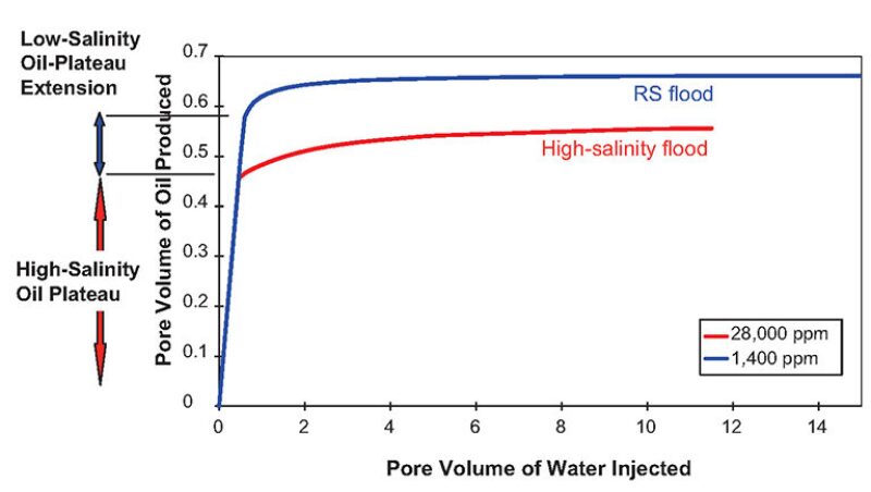
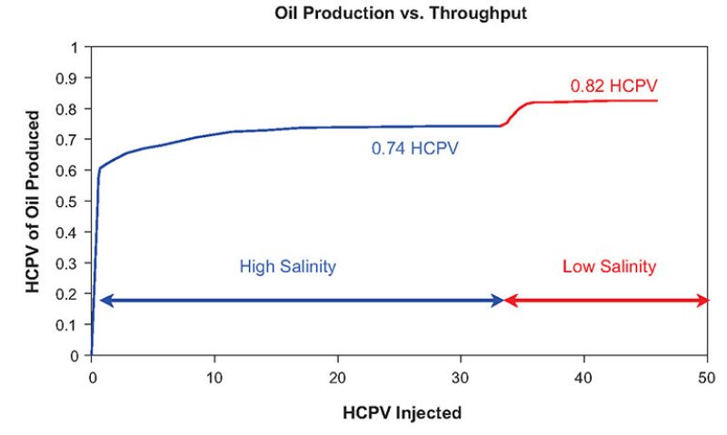
Full-reservoir-condition RS EOR corefloods have been performed on many reservoir systems across the world. All tests have shown similar characteristics, with increased oil production at water breakthrough and a decrease in remaining oil saturation at the end of the waterflood tests. RS EOR recovers additional oil after both secondary (RS water injection from Day 1) and tertiary (RS injection following higher-salinity-water injection) waterflood applications. Fig. 1 and Fig. 2 show typical secondary and tertiary responses to RS EOR, respectively.
The mechanism for release of additional oil has been inferred from laboratory tests. Organic components in crude oil are attracted to surfaces through a mechanism explained by the Derjaguin-Landau-Verwey-Overbeek theory of colloid stability. The mechanism by which polar organic species in the oil become attached to charged surfaces involves, in several cases, cation bridges. RS brines are able to break the organic-molecule attraction to the surface by exchanging the divalent cation for a monovalent cation such as sodium.
Selection and Description of Membrane Technologies for RS-EOR Facilities. Facilities studies considered numerous desalination technologies and identified the most suitable, proven technology for the desalination of seawater offshore to be membrane desalination protected upstream by membrane prefiltration to minimize effects on weight and space.
Membrane desalination relies on ion rejection by reverse osmosis. The process requires application of pressure to the seawater feed to drive water molecules through semipermeable ion-rejection membranes, overcoming the osmotic potential of the seawater and generating RS permeate and more-concentrated retentate (or brine) streams. Upstream, membrane filtration provides the high levels of suspended-solids, organic matter, and bacteria exclusion necessary to limit fouling and maintain operability of the desalination process. The filtration-membrane efficiency is maintained by regular, frequent backwash cycles.
Robust Laboratory Analysis
RS Coreflood Testing. In support of deployment of RS EOR in Clair, a number of corefloods were performed. These tests were conducted at full reservoir temperature and -pressure conditions with live fluids.
Core Characterization and Selection. Intact core pieces were scanned routinely with computed tomography to aid selection of plugging points and to ensure minimal heterogeneity (especially fracturing and lamination). The plug samples were cleaned by miscible solvent and had their permeability and porosity measured by flow-through methods.
Acquisition of Initial Conditions. The samples were set to initial water saturation by the porous-plate method, and the samples were then loaded into a test rig and degassed by injection of refined laboratory oil. The samples were then saturated with live (i.e., gassed) recombined Clair oil. The samples were aged for 3 weeks, with weekly refreshes of the resident oil.
Coreflood Experimentation. For secondary recovery, the samples were water-flooded with RS brine in an unsteady-state mode at a low rate of approximately 4-cm3/h injection in the laboratory. During this test, oil production was recorded and saturation was monitored in situ. At the end of the test sequence, the RS brine was displaced with a doped brine to obtain good in-situ saturation endpoint data. The benefit associated with RS EOR in the secondary mode was then assessed by running a regular coreflood using connate brine on a sample cut from the same core piece and exhibiting properties that were as similar as possible.
Experimental Results. Plugs from the main field experienced significant benefits from secondary flooding across both of the permeabilities tested, with a shift of 5.5 saturation units and 7.9 saturation units in the two tests. These benefits were observed at residual oil saturation and as an increase in dry-oil production.
Subsurface-Process Evaluation Efficiency
Having seen evidence of a material RS EOR oil response from special core analysis of the Clair rock/fluid system, it was recognized that an upscaled view of the expected Clair Ridge RS EOR incremental-oil-recovery profile would be required to justify the incremental capital expenditure associated with RS EOR facilities.
An initial sensitivity study covering RS EOR residual-oil uncertainty, capillary pressure uncertainty, and reservoir-description uncertainty confirmed that reservoir description had the largest effect on RS-EOR incremental oil recovery at Clair Ridge. Although a full-field model (FFM) of the Clair Ridge existed, 2-day FFM run times and the wide range in underlying reservoir-description uncertainty combined to drive the project toward adoption of sector modeling to investigate and upscale Clair Ridge RS-EOR oil-recovery predictions.
Sector-Model Description. A range of 48 reservoir-description types were defined as plausible across the Clair Ridge structure by combining possible joint and subseismic fracture descriptions. RS-waterflooding performance across this range was evaluated using a single-porosity sector-model volume cut out from Clair Ridge. The sector model contained a producer/injector pair at reservoir-scale interwell spacing. Across all reservoir-description types investigated, fractures and matrix were both modeled explicitly.
The effect that this range of reservoir fracture/matrix descriptions could be expected to have on RS EOR incremental oil recovery was investigated by simulated waterflood of each reservoir-description type. BP’s Top Down Reservoir Modeling technique was used to build a sector model for each reservoir description and then to execute separately both a high-salinity and an RS waterflood through that same reservoir description. Comparison of RS waterflood oil-recovery performance against high-salinity-waterflood oil-recovery performance allowed an incremental RS EOR type response to be generated for each reservoir description.
Sector-Model Results. Fig. 3 shows incremental RS EOR recoveries for the 48 models at end of field life ordered by increasing recovery. There is a positive RS EOR incremental oil recovery from 98% of the reservoir descriptions tested. The average incremental oil recovery across all descriptions is clearly positive.
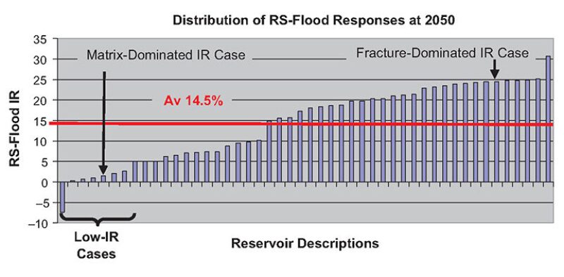
Further investigation into the below-average recovery cases seen in Fig. 3 confirmed that low-recovery cases are associated with matrix-dominated reservoir descriptions where the fracture density is low and the fracture network poorly connected. In such reservoir descriptions, injectivity is pressure limited and the flood-front progression under both high-salinity and RS waterfloods is slow. When such matrix-dominated reservoir descriptions are waterflooded across an interwell distance, the arrival time of incremental RS-EOR oil is delayed to the extent that it is only just beginning to manifest itself at the end of field life.
Sector-Model-Results Upscaling. On the basis of core, seismic, and log data, a Delphi analysis (a systematic approach that started with individual experts’ views that were subsequently discussed and revised to achieve a consensus view) was completed by members of the Clair Ridge subsurface team to define the volumetric significance (within the Clair Ridge reservoir) of each of the 48 fracture/matrix descriptions considered in the RS-EOR sector-modeling study. Normalized RS-EOR incremental oil recovery profiles from each of the 48 sector models were then combined on a volume-weighted basis into a single normalized rock-volume-weighted (RVW) type response.
With the aim to reinject produced water, an evaluation was conducted to determine the optimal location and timing for injecting produced water and RS water across the various reservoir compartments. Produced-water reinjection and RS-waterflood injection can be considered to be mutually exclusive for a given water-injection well. Therefore, understanding where produced water can be disposed of across the field defines the injectors that will not take produced water and, by implication, the injectors that can take RS-waterflood injection.
Having understood the sequence of Clair Ridge reservoir segments to experience RS waterflood, a Clair Ridge upscaled RS-waterflood incremental-oil-recovery profile was created by applying the normalized RVW-type response to the underlying high-salinity-flood oil-recovery profile associated with each Clair Ridge segment to experience RS flooding.
This article, written by Special Publications Editor Adam Wilson, contains highlights of paper SPE 161750, “Low-Salinity Enhanced Oil Recovery, Laboratory to Day-1 Field Implementation—LoSal EOR Into the Clair Ridge Project,” by Enis Robbana, SPE, Todd Buikema, Chris Mair, SPE, Dale Williams, Dave Mercer, Kevin Webb, SPE, Aubrey Hewson, and Chris Reddick, SPE, BP, prepared for the 2012 Abu Dhabi International Petroleum Exhibition and Conference, Abu Dhabi, 11–14 November. The paper has not been peer reviewed.