Advances in modeling techniques allow quantitative prediction of long-term trends in cuttings-pile characteristics and environmental risks, providing firm direction in mitigating risks. Modeling involving fluid dynamics, soil mechanics, scientifically verified 3D dispersion modeling, contaminant degradation, and seabed recovery was used in several scenarios: the extant pile, moving the pile across the seabed using suction pumps, backflush discharges related to retrieving the pile, and disturbance from remaining jacket footings ultimately falling into the pile after several hundred years.
Introduction
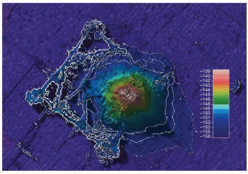
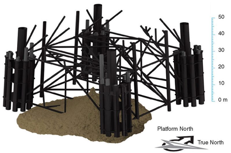
The Murchison platform is located in 156 m of water in the northern North Sea and is operated by CNR International. Drilling operations had been conducted at the field since the 1970s, ending in 2008. Discharges of drill cuttings and drilling mud have resulted in the formation of a drill-cuttings pile beneath the platform jacket structure. Between 1980 and 2000, oil-based muds were used and oil-contaminated discharges took place in line with normal permitted operations, and the cuttings pile now in place is consequently oil-contaminated. Fig. 1 shows the location of the Murchison platform and the local bathymetry, and Fig. 2 illustrates the jacket base.
The Convention for the Protection of the Marine Environment of the North-East Atlantic (OSPAR) Commission Recommendation 2006/5 sets out a management regimen for such oily-cuttings piles, depending largely on thresholds against which the level of pollution attributable to a historical cuttings pile may be measured in order to determine whether the level of pollution could be significant. An assessment of the Murchison pile was submitted to the commission in 2008 as part of the regulator’s implementation report, concluding that the Murchison pile did not exceed the relevant criteria and that it could be left to degrade by natural processes. For those piles that can be demonstrated to have characteristics below OSPAR thresholds, the recommendation states that no further action is required and that the cuttings piles may be left in situ to degrade naturally.
The Murchison field is in the process of being put forward for decommissioning, and the assessment made in 2008 regarding the rate of oil loss and the persistence footprint has been re-evaluated. By use of records of the discharges made from the platform, survey data from the Murchison cuttings pile, and industry data sources on the composition of drill-cuttings piles, a model of the existing pile has been constructed and used to understand the present condition and long-term fate of the pile.
Approach
The original drilling discharges were modeled by use of the dose-related risk and effect assessment model (DREAM) published by SINTEF, which incorporates the ParTrack submodel used for modeling dispersion and settlement of solids. The model predicts the fate of materials discharged to the marine environment.
DREAM can also calculate an estimate of risk to the environment by use of a metric known as the environmental-impact factor (EIF), based on the ratio of the predicted environmental concentration to the predicted no-effect concentration (PEC/PNEC ratio). A species sensitivity distribution is applied to each stressor to identify a PNEC, and PEC/PNEC ratios are calculated for the individual stressors identified as relating to drill cuttings (e.g., toxicity of chemicals and oxygen depletion). This allows the model to combine and compare the contributions of different stressors to the overall risk, known as the potentially affected fraction (PAF). The level of 5% PAF is a generally accepted risk level, and as such, the EIF value is taken as the spatial extent over which the multistressor PAF exceeds 5%.
The model has been developed to calculate the dispersion and deposition on the seabed of drilling mud and cuttings as well as the dispersion of chemicals in the free-water masses and has been validated in the field. The calculations are based on a Lagrangian, or “particle,” approach combined with a near-field plume model and the application of external current fields for time- and depth-resolved currents.
Application
The data set comprises 4 years of single-point current data (1989–92) for the Murchison location at eight depth bands through the water column. The data set is repeated in the model to produce currents spanning the period from 1980 to 2001. Wind-driven forcing of the surface currents is not included in the modeled currents, and the cuttings deposition in water depths of 156 m is not expected to be affected by the shallow surface conditions. The model takes into account the thermocline and halocline. (For a detailed discussion of the Murchison mud and cuttings discharges, please see the complete paper.)
Oil Composition. A variety of different oil types have been used throughout the Murchison drilling program. Within each type, there might be several possible formulations. There are no definitive records available to identify what was used. Therefore, assumptions have been made about the general type of oil used on the basis of the years when drilling took place (i.e., diesel-based, low-toxicity oil, and synthetic oil). Each of these generic types is composed of a variety of specific oil components. Typically, these can be categorized into groups with similar properties, including aliphatic oil, benzene and alkylated benzene [benzene, toluene, ethylbenzene, and xylene (BTEX)], naphthalenes, and polycyclic aromatic hydrocarbons (PAHs).
Results
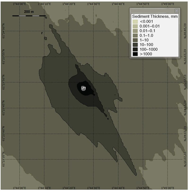
Re-Creating the Extant Pile Within the Model. Predicted Sedimentation Levels. Predicted deposition thickness of the drill cuttings and drilling mud over an area of approximately 8×8 km around the release point is shown in Fig. 3. This indicates that the majority of the cuttings deposits are close to the discharge point while a smaller proportion distributes over a wide area to a low thickness. The greatest accumulation of cuttings is beneath and slightly to the southeast of the release point, reflecting the prevailing currents in the area.
Oil Concentrations in the Sediment. Concentrations are predicted at the end of the discharge period, and then at a number of years subsequently (1, 2, 5, 10, and 20 years). It is possible to view each hydrocarbon type separately in the model, and it can be seen that overall, after 20 years, the concentrations of oil are still dominated by aliphatic hydrocarbons, which are an order of magnitude higher in concentration than PAHs. The model predicts that BTEX and naphthalenes degrade relatively quickly, and that hydrocarbons in the thinner areas of deposition degrade much more quickly than those in the deposits of several centimeters or more.
Mass of Oil Lost From Pile Over Time. The amount of oil loss from the pile (i.e., from all the deposition within an 8×8-km area around the discharge point) is seen to begin at a rate of 119 t/a over the first year after discharges ceased, dropping rapidly over time to less than 5 t/a at Year 20 and beyond. The high initial rates could reflect the relatively high biodegradation rates of BTEX and naphthalene and the fact that most oil reduction appears to take place in the thinner areas of deposition.
Area of Seabed With an Oil Concentration Above 50 mg/kg. Because a gradually reducing footprint remains on the seabed, the area multiplied by the duration (footprint×persistence) will increase slowly over time. To understand whether this might, at some point in the future, reach the OSPAR criterion, the trend was translated into a power relationship with time and then predicted into the future. It was calculated that the forecast of footprint×persistence over time would not exceed the 500 km2×years criterion, even projecting over thousands of years.
Environmental Risk to the Seabed. The modeling predicts that, at the end of the simulation (i.e., the end of 2019), areas where the risk is greater than 5% are predicted to be contained within approximately 1 to 2 km of the well. Overall environmental risk is predicted to be dominated by PAH content, reflecting its modeled persistence and toxicity. Oxygen depletion (and consequential increase in sulfide concentration) is also significant, reflecting the concentrations of biodegradable oil present. Other factors are predicted to be much less significant, including heavy metals, burial thickness, and grain-size change.
Moving the Cuttings Pile. Because the cuttings pile obscures part of the jacket, certain jacket-decommissioning issues are contingent on the removal of the pile to allow access to the jacket.
A second modeling exercise examined the effects of pumping drill cuttings from below the Murchison platform to an area on the seabed located 70 m from the center of the platform. In this scenario, the pile is modeled with a degree of degradation of the oil and a distinction between the main layers of degraded mud on the surface, a relatively undegraded oily core, and a bottom layer representing the original tophole and water-based-mud cuttings. Two pumping regimens were modeled in relation to the number of locations to which the pile is being pumped, and for each of these, a range of water/solid ratios and work timespans was modeled to account for the uncertainty associated with this procedure.
Collapse of the Structural Piles. The possibility exists that, even during decommissioning, the jacket footings may remain. A further modeling exercise was undertaken to examine the effects of disturbance of the existing cuttings pile below the Murchison platform caused by the ultimate collapse of the structural piles that surround each jacket leg should both the structural piles and the cuttings pile be left in situ. This collapse is something that could happen in several hundred years’ time, given expected corrosion rates. The cuttings themselves would be significantly weathered and degraded by this time.
An exercise in fluid mechanics was undertaken to calculate the velocity of a falling pile as it strikes the cuttings pile, taking drag into account. A second exercise in soil mechanics was undertaken to model the displacement of cuttings as the energy of the falling pile is converted into mechanical movement of the pile and ejection into the water column. The approach taken was expected to lead to an order-of-magnitude estimation of the potential effects.
The majority of resuspended material was predicted to deposit within 1 km of the cuttings pile, while finer components will travel considerably farther. The peak thickness of deposition was approximately 3.5 mm from a single pile failure, and 27.5 mm for all the piles failing, which is predicted to occur within 40 m of the discharge point. Thicknesses rapidly diminish with distance.
For a scenario in which all the structural piles collapse within 1 year of each other, risks to the seabed above a level of 5% are predicted to occur initially up to 1 km from the cuttings pile in the most-pessimistic scenario, reducing over time to within 500 m after approximately 1 year. A small area of contamination is predicted to persist for more than 20 years within 200 m of the cuttings pile. This is also likely to be the area that retains historical contamination and therefore might not represent a significant change to the underlying conditions.
This article, written by JPT Technology Editor Chris Carpenter, contains highlights of paper SPE 164983, “Modeling the Options for Managing Drill-Cuttings Piles on Decommissioning,” Sean Hayes, SPE, Genesis, and Liz Galley, CNR International, prepared for the 2013 SPE European HSE Conference and Exhibition, London, 16–18 April. The paper has not been peer reviewed.