In one Saudi Aramco offshore oil field, the production from different platforms is transported to an onshore gas/oil-separation plant (GOSP) where the produced water is removed from the hydrocarbon stream. Then, the produced water is injected continuously into highly permeable formations through disposal wells. Therefore, the water-disposal system is an integral part of the hydrocarbon-recovery system. Failure of one of the disposal wells could affect oil production adversely.
Introduction
Field A is a mature oil field with more than 500 active producing wells, and it has been on stream for more than 50 years. The crude-oil-handling facility was built onshore with limited equipment capacity and a limited water-disposal capacity. The field produced formation water beginning in the 1980s, and the water cut has increased over time. This field is expected to continue operating at approximately full crude-oil-handling capacity, with all produced water to be disposed of continuously. The main focus is how to maintain the ability to dispose of all the produced water.
Of the options studied, the best was to drill new water-disposal wells and to service existing disposal wells to maintain a high disposal capacity. Evaluation of the disposal capacity of each well is the core part of this option and is a major challenge associated with a water-disposal system. Well tests on water-disposal wells are uneconomical to conduct monthly. Also, water injection would have to be interrupted during testing.
Another major challenge was determining an effective treatment for water-disposal wells that have encountered a significant drop in injection potential. The produced water contains a significant amount of waste material including solids, salts, chemicals, and residual oil. Even after being treated, the wastewater causes pipeline corrosion and formation damage. Conventional acidizing with hydrochloric acid (HCl) or mud acid (12% HCl+6% hydrofluoric acid) proved ineffective for treating the formation damage to improve injectivity. A new way was found for dealing effectively with injection loss caused by specific formation damage.
Water-Disposal System
The produced water passes through high- and low-pressure separators and then is pumped to the disposal wells by two injection pumps and a 24-in. above-ground pipeline. Because the water-disposal system is part of the hydrocarbon-recovery system, reduction of produced-water injection would restrict oil production. An increasing number of wells have electrical submersible pumps (ESPs) installed to produce fluid at higher rates, which accelerates water production. With new ESP wells coming on stream, in a few years the water volume will be two and one-half times the current produced-water volume.
During the 1990s, the disposal system was determined to have pipeline- and downhole-tubular-corrosion issues. The corroded pipeline and tubulars generated corrosion byproducts that plugged the formation pore throats when carried downhole with the injection water. Laboratory analysis showed that the main components of the corrosion byproducts were iron oxide and iron sulfate. In addition, a small amount of oil in the water (especially the heavy-oil component) was trapped by these corrosion solids, creating a barrier either in the near-wellbore region or on the face of the formation. Early attempts to bypass the altered zone with massive HCl or mud-acid treatments were not effective.
In 2003, Saudi Aramco began trying different ways to stimulate the water-disposal wells to improve injectivity. Initially, wells were stimulated with nitrified water for cleanup, with good results. A service company was contracted to develop a combination of chemicals specifically for removing the oil and the corrosion byproducts deposited in the tubulars, on the face of the formation, and in the near-wellbore region. Wells were treated with three chemicals in separate stages yielding excellent results. To date, 20 such chemical treatments have been performed, all with a positive response. Therefore, all water-disposal wells, even newly drilled water-disposal wells, are treated in this manner.
Well-Performance Monitoring
Well surveillance can identify potential problems at the earliest time to restore the expected injection rates by taking remedial action. The injection rates and injection pressures are used to monitor well performance. Injection rates fluctuate over a short period of time, but over a longer period of time rate change reflects the qualitative change of formation properties. The injection rate can be measured by different metering systems. Three types of metering systems have been tested: solar-powered flowmeters (SFMs), ultrasonic meters, and chart-type meters. It was shown that the SFMs and the plant meters matched with less than 1% discrepancy. The SFMs, and the ultrasonic and plant meters all have very close readings, with a maximum discrepancy of 5% that verified the accuracy of the water-injection metering systems. The accuracy of these meters is essential to allocate water production from the field.
Analysis of Injection Drop
Frequently, formation damage occurs in the near-wellbore region of production and injection wells, where conditions vary significantly. Formation damage can occur throughout the reservoir as production continues, especially when asphaltene deposition and scale formation occur. The reservoir contains various mineral oxides along with swelling and nonswelling clays. Subsequently, other substances, such as drilling mud, hydraulic-fracturing fluids, cement, and debris, may invade the reservoir.
Water separated at the GOSP contained variable amounts of oil and suspended solids. Oil saturation will increase in the near-wellbore region, decreasing brine permeability. Heavy hydrocarbons and asphaltene can precipitate and block some of the pore throats. Rock-wettability changes, caused by organic deposits, are possible. To remove potential damage from oil invasion in Well A, and to restore injectivity, 2,200 gal of xylene (5 gal/ft of perforations) followed by 2,000 gal of a solution containing 10 vol% mutual solvent and 0.2 wt% water-wetting surfactant was circulated in the wellbore. These chemicals should remove heavy hydrocarbons and restore rock wettability. The well was backflowed to the surface, where a large amount of oil was recovered. However, well injectivity remained low, with an injection rate of 3,000 BWPD at 2,200-psi injection wellhead pressure (IWHP). Normally, the well would take at least 30,000 BWPD at 1,200-psi IWHP. Therefore, the well was still damaged and further treatments were required.
If particulates are larger than the average pore-throat diameter, the particles cannot penetrate the pores, resulting in an external low-permeability filter cake. This type of damage occurs very fast. The degree of plugging and the extent of injectivity decline depend on rock characteristics (i.e., permeability and porosity), oil content and oil-drop-size distribution, flow velocity, and total suspended solids.
Another type of injectivity impairment occurs when the size of the particles in the injection water is smaller than the average pore-throat diameter. These particles will invade the formation and bridge smaller pore throats. As the concentration of solids in the injection water increases, the rate of permeability decline becomes greater.
Falloff tests were used to identify formation-damage problems. Analysis revealed formation damage, which required further investigation. The injected-water quality primarily controls the severity and frequency of formation damage. Therefore, water-disposal-well monitoring consists primarily of two parts. One is the injection rate. The other is injected-water quality, by obtaining and analyzing water samples regularly.
Treatment and Evaluation
After performing 11 massive HCl and mud-acid stimulations on water-disposal wells, it was concluded that neither a small acid wash nor massive acidizing (30,000 gal of acid) was effective. In 2002, fluid-bailer samples were taken from seven water-disposal wells. Samples of the sediments in those wells were obtained during workover activities. Compositional analysis indicated that the material consisted largely of corrosion materials (iron oxides, sulfates, carbonates, and sulfides), scale-type materials (calcium carbonates and sulfates), silica as sand, and sodium chloride. The sediments also contained 12 to 38% hydrocarbon.
In 2007, eight fluid samples were taken either from the wellhead or downhole. The analysis indicated that the sediment material consisted largely of corrosion materials (iron oxides, sulfates, carbonates, and sulfides), scale-type materials (calcium carbonates and sulfates), silica as sand, and sodium chloride.
Wellbore Treatment
The complete paper details three case studies. One is summarized here.
Well-A—Vertical Water-Disposal Well. The well was drilled and completed as a vertical cased-hole water-disposal well in 1981. During the initial completion, the well was acid washed with 5,000 gal of 15% HCl. Production logging showed an injection rate of 6,500 BWPD at 1,000‑psig IWHP. The well was put on injection in July 1982 with three other disposal wells. The performance of the subject well was monitored by conducting annual production logging and injectivity tests. All injectivity tests indicated a positive skin factor in this well. Several workovers were performed after 1984, attempting to remove the damage and to improve the injectivity, but with no success. Before 2002, well interventions with a coiled-tubing unit were conducted with similar results and were not successful.
A pilot chemical treatment was conducted on this well starting in February 2003, with sufficient volumes of mutual solvent to dissolve hydrocarbon residue in the tubulars and on the sandface and with chemicals to strip away any filter cake on the sandface. Two weeks after this treatment, an injection test showed that the injection rate increased by approximately 12,000 BWPD at 1,020-psig IWHP. A similar chemical treatment was conducted on two other wells, with similarly encouraging results. Fig. 1 shows the treatments and their effects.
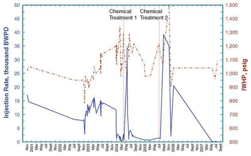
A workover sidetracked the subject well into the K zone with a barite-weighted oil-based mud. Analysis revealed that severe formation damage may have been caused by the weighting material. Another customized chemical treatment was planned and executed to remove barite by use of barite solvent. Nitrogen was pumped to facilitate flowback. Subsequent injectivity tests indicated a rate of 12,000 BWPD at 1,200‑psig IWHP. Although the treatment improved the injectivity, the subsequent decline in the injection rate indicated that additional debris had plugged the newly treated zones after the stimulation treatment.
In 2004, another stimulation treatment (Chemical Treatment 1 in Fig. 1) used a special HCl recipe. This treatment increased the injectivity by 23,600 BWPD. The injection rate declined greatly in a short period of time. Bailer samples were taken from two injection wells, and fluid samples were taken from the plant. Analysis showed higher-than-normal iron content, and the bailer samples contained corrosion byproducts consisting mainly of hematite, magnetite, iron oxide, iron sulfate, and iron sulfide.
Another chemical treatment (Chemical Treatment 2 in Fig. 1) used one additional stage to dissolve iron compounds. Nitrogen was used to facilitate the flowback. Fluid samples were obtained and analyzed during the treatment to monitor the iron content. After the treatment, an injection test showed that an injection rate of 39,200 BWPD at 1,150-psig IWHP was obtained.
Future Work
The current focus is on surveying the quality of the injected waste water. Permanent meters and instrumentation are being installed on individual wells. Those meters will be linked to a supervisory control and data-acquisition system to enable remote real-time monitoring and reporting of production from each well and injected-water quality at points from the injection pumps to each wellhead. From this system, the water quality is determined on the basis of the concentration of oil in water, pH value, iron concentration, and the total suspended solids. In addition, the IWHP and injection rate are monitored and recorded to allow further investigation of each well. Real-time monitoring enables making quick decisions and implementing action plans. It is expected that the interval between two treatments on one water--disposal well can be prolonged with the new surveillance system.
This article, written by Dennis Denney, contains highlights of paper IPTC 16595, “Formation Damage and Treatment of Offshore Water-Disposal Wells in Saudi Arabia: Case Studies,” by Ken Mei, Hassan B. Qahtani, Abdulmohsen S. Al-Kuait, and Luai A. Sukkar, Saudi Aramco, prepared for the 2013 International Petroleum Technology Conference, Beijing, 26–28 March. The paper has not been peer reviewed. Copyright 2013 International Petroleum Technology Conference. Reproduced by permission.