
Editor’s Note: If you have a new technology introduced fewer than 2 years ago and would like to highlight it in Young Technology Showcase, please contact JPT Technology Editor Chris Carpenter.
Introduction
Stuck pipe has traditionally been a challenge for the oil and gas industry; in recent years, operators have become even more determined to reduce the effect of stuck-pipe issues. Even with the best planning and practice, there is a significant probability in certain wells that some of the string will not come back out of the hole. While losing a bottomhole assembly is never ideal, the time wasted in trying to free it and in redrilling afterwards can be far worse.
HyPR HoleSaver
The results of Churchill Drilling Tools’ collaboration with drilling crews in the North Sea and the Gulf of Mexico and extensive research and development resulted in the creation of the HyPR HoleSaver, the first hydraulic pipe-recovery system. In March 2015, the system had its first major deployment, optimizing stuck-pipe contingency in zones highly vulnerable to differential sticking. Although no stuck-pipe issues arose, the tool significantly reduced the cost-overrun risks. The tool is now being considered for imminent deployment by a number of other major operators and leading independents, to reduce costs and risks in a wide range of upcoming wells across the globe, particularly in the Gulf of Mexico.
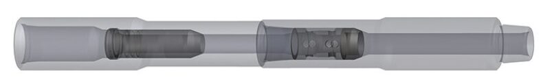
The tool consists of a full-strength sub positioned in the drillstring, which is severed in a couple of hours (Fig. 1). A jetting dart is launched and lands inside the sub, jetting the internal American Petroleum Institute (API) pin connection.
At the conceptual stage, a number of questions had to be considered. Could significant time savings actually be delivered from the point at which the decision is made to sever the string until sidetracking or fishing commences? With its expertise in dart-activated tools, Churchill Drilling Tools decided to determine whether applying dart-related principles in a new approach could cut wait times significantly.
The Need for a New Method
A major delay in severance often accompanies the mobilization of specialist equipment or personnel. This is compounded in remote locations or when moving restricted equipment, such as explosives or hazardous chemicals. Ideally, any new method should be self-operated by the user, or at least should allow cutting-and-retrieval operations to begin while third-party services are mobilized.
As strings become more sophisticated, each additional element has the potential to upset others. Not only must the sub have full structural integrity, it must also be totally benign as far as other tools are concerned. In practice, this means being wider in internal diameter (ID) than any lower component and with fully compliant and tapered lead-ins to ensure all activating devices (and flow) have an unrestricted path through the tool.
The weakest point in every joint is normally the pin; if that area were targeted with enough energy, then perhaps it could be sufficiently weakened, for parting to be achieved by merely pulling and twisting the pipe. Calculations quickly confirmed that removing only half the pin ID would put most connections in this breakable range. The logical solution was to use a dart to focus energy from the mud pumps precisely onto the weak point.
Research and Development Leads to Proven Performance
The first objective was to establish the feasibility of making deep cuts into connections using only hydraulics. Initial testing confirmed that the first few millimeters of steel could be claimed within just 10 minutes. Tests were short-lived, however, because they highlighted the major design challenge for the system (Fig. 2 above).
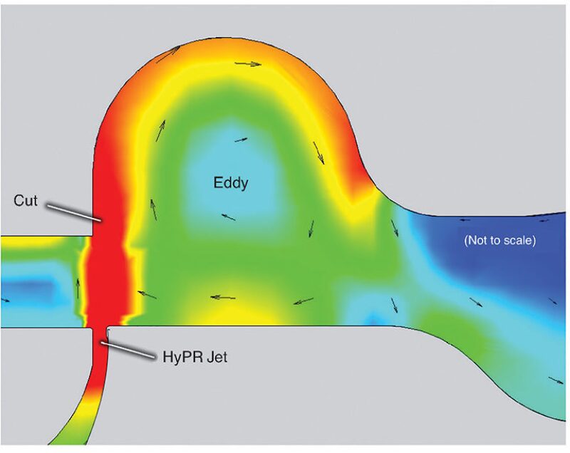
Depending on gap size, the energy dissipated or produced by the jets at 350 gal/min is approximately 250 hhp. Therefore, the dart assembly has to sustain very high loads as it deflects the flow at right angles and accelerates it up to 300 ft/sec through the nozzle. The jet and resulting eddies generate harmonic effects that amplify the stresses on vulnerable zones in the assembly (Fig. 3). Initial designs were not able to survive much more than 10 minutes of flow.
In a secondary version, the seat was relocated from the tail to the nose of the dart. While this would add complexity, in terms of the need for bypass channels around the seat region, it would greatly increase the stability by effectively removing an unsupported cantilever oscillating in the wake of the jet. At the same time, priority was given to maximizing the safety factors to remove the possibility of structural failure. By having the seating below the jet, the dart can be left behind after cutting, because it is no longer held in the top half of the sub. This enables the recovered pipe to be clear after cutting, enabling cementing of a sidetrack plug immediately.
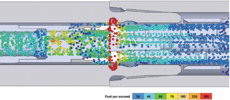
As the darts became stronger and longer tests became possible, patterns of washing began to be discernible on both the target pin region and the dart itself. As expected, there was a dramatic wearing just below the pin in the target region; however, a smaller secondary eddy also appeared farther down the wake, as well as a short eddy zone just in advance of the jet (Fig. 4). While immaterial to the cut, this wear geometry had implications for the integrity of the dart.
It was clear that the high-velocity zones on the steel dart were not being totally defended by their tungsten carbide coatings. The deflection, jet, and eddy regions on the dart were all showing signs of washing in the coatings. The materials in these zones were therefore replaced with solid-ceramic assemblies.
Once it was established that the system was working, attention switched to establishing the performance envelope. Variables such as mud type, particle size, jet size, flow rate, and connection size have an effect on the load on the dart and on the speed of the cut. The test program was performed on a full land-rig setup with twin 12-in.-stroke triplex pumps and was designed to model a full range of scenarios, from slimhole to deep water. The performance envelope is bounded first by the circulating-system power and pressure capability; next by the particle size, which limits the tightness of the jet and therefore the jetting velocity; and then by the the power limits of the dart in terms of physical integrity. It was clear from the data that it was not necessary to push close to the limits of the envelope because the cutting is very fast, even at lower flow rates.
Consistent with Churchill Drilling Tools’ existing range of choked darts, the new tool’s dart is designed for free fall and for pumping into place, with a pressure increase confirming landing. As expected, the tests showed that the user would see falling pressure within a few minutes of landing as the ID of the pin started to wash. They also showed that, once the initial cut is made, pressure falls become less indicative as to the progression of the cut and there is not a specific pressure indication for the pin approaching its yield point. Applying a small amount of pull during cutting will part the pipe when the time comes, and the positive result will be self-evident.
From a Weakness to a Strength
Since the tool’s launch, Churchill Drilling Tools has been approached to provide the technology for abandonment operations, adding preplanned applications to its capabilities alongside contingency roles. The dormancy mode allows it to turn abandonments into single-trip operations, providing the potential for on-demand pipe or casing cutting with improved cutting performance.
Critical to the effective deployment of the tool is the common pin, so often considered to be the weak spot in string design. Now, the pin has a new and central role to play, proving that innovative thinking can change a traditionally perceived weak point into an actual strength in solving stuck-pipe problems.