
This paper describes the preplanning and execution of Australia’s largest subsea well-abandonment campaign to date. The Jabiru and Challis fields are located in the Timor Sea, 640 km from Darwin, Australia. The fields consist of 13 subsea producers and six suspended or partially abandoned wells. The paper describes actual experience in a relatively uncommon operation in the industry and includes learnings that can be applied to future development planning.
Introduction
The Jabiru field was discovered in July 1983, with a total of 17 wells drilled to appraise and develop the structure. The field was developed with five subsea production wells tied back to a floating production, storage, and offtake (FPSO) facility. Water depth is approximately 120 m. In addition to the five subsea producers, there were three suspended or partially abandoned wells in the field.
The Challis and Cassini fields were discovered in October 1984 and June 1988, respectively. Cassini is a single-well satellite field, but for the purposes of this paper has been classified as part of the Challis field. In total, 18 wells were drilled to appraise and develop the structure. Production commenced in December 1989 and ceased in September 2010. The field was developed with eight subsea production wells tied back to an FPSO facility. Water depth is approximately 110 m. In addition to the eight subsea producers, there were three suspended or partially abandoned wells in the field.
It was originally intended to carry out the entire abandonment in one continuous program. However, time pressures required two phases. The four simplest wells were moved forward into a Phase 1 program and carried out at the beginning of the rig campaign. The remaining wells were abandoned in Phase 2 following the drilling of three exploration wells. A semisubmersible rig was deemed best for the project.
Preplanning
There were four wells that were already abandoned subsurface to the extent that only wellhead removal was required. To assist in planning, the remaining wells that all required re-entry and subsurface abandonment were divided into abandonment types. Five types were identified, as follows:
- Type 1 (two wells): These wells had been abandoned partially and required an additional deep cement plug and wellhead removal.
- Type 2 (seven wells): These wells were all development wells with completions installed. They were all producing close to or up to the point of field shutdown, with no reports of significant well problems. It was therefore planned to carry out a through-tubing abandonment to avoid nippling up the blowout preventers (BOPs).
- Type 3 (one well): This well suffered a leak and required a workover in 2005 to run a 7⅝-in. tieback as the new production casing. This configuration gave the well a unique classification.
- Type 4 (two wells): These wells suffered known tubing leaks and therefore required the tubing to be pulled.
- Type 5 (three wells): These wells had indeterminate annular cement behind the production casing. The tubing therefore had to be pulled to allow a cement-bond-evaluation tool to be run to assess the annular hydraulic isolation to determine if remedial cementing was required.
Reservoir and Geological Analysis
A detailed study of the reservoirs and overlying geology was undertaken to establish what zones required permanent isolation. The originally normally pressured reservoirs contained 40 °API oil with a small gas cap. The reservoir pressure had depleted, and the wells required gas lift to produce. The reservoir layers are in vertical geological communication, and each reservoir has a common original oil/water contact and oil gradient. There are no distinct permeable zones with varying pressure regimes; therefore, zonal isolation was not required within the reservoir. This meant that the cement plug did not have to extend below the production packer to effect adequate hydraulic isolation.
Although the wells were depleted, there was a strong regional aquifer. It was therefore conservatively assumed that, over time, reservoir pressure would build up to its original value. The depth at which formation-fracture pressure is able to sustain migrated original reservoir pressure was calculated for each reservoir. These depths provided the minimum acceptable depth for the cement plugs.
The geological analysis indicated that it was acceptable to leave the 9⅝×13⅜, 13⅜×20, and 20×30-in. annuli open as long as there were two acceptable permanent barriers below, and the casing shoe was above any closure. The structural seal was immediately above the reservoir. An abandonment plan was developed for each well, to account for unique features.
Abandonment Methodology
The primary method of well abandonment for Type 2 wells was to bullhead cement plugs into place. The condition of the production casing was a significant unknown. Caliper logs and workovers on several wells demonstrated that the tubing was suffering from corrosion. Because of concerns about the poor integrity of the 9⅝-in. production casing, it was decided to minimize applied pressure during the abandonments and not to pressure test the cement plugs. Plug verification was instead to be carried out by tagging only. In both fields, the flowlines were flushed, the tree valves were pressure tested, and the FPSOs were removed. The gas lift annuli on Jabiru were bled off, but the annuli on Challis were left full of lift gas contaminated with hydrogen sulfide because the swivel on the single-anchored-leg mooring (SALM) developed a leak before the depressuring could be carried out.
In addition to tubing-integrity concerns, there was the potential for the tubing to contain naturally occurring radioactive materials (NORM). The prospect of recovering potentially badly corroded tubing coupled with NORM contamination was daunting, and therefore through-tubing abandonments were carried out wherever possible in order to maximize the amount of tubing left in situ.
Abandonment Design. The two main types of planned abandonments were through-tubing abandonment and pulling of tubing. The latter was to be used to access the 9⅝-in. casing to evaluate annular cement or in cases where the tubing integrity had been compromised, negating the possibility of using the tubing as a cementing conduit.
Outline abandonment procedures, contingency plans, and details about subsea-equipment preparation are covered in detail in the complete paper.
Barrier Management. A number of the barriers that were in place during the well construction were no longer present. Additionally, it was anticipated that some barriers that could normally be relied upon may not be available once the well was re-entered because of the age and reliability of equipment. Lack of integrity also meant that the verification of new barriers by pressure testing was difficult. The base plan was to kill the tubing by bullheading and then set a bridge plug in the packer tail pipe. The annulus would then be killed by either circulating or lubricating in kill fluid. Flow charts and matrices were developed to identify where barriers were known to be missing or could potentially be unavailable, and contingency plans were developed accordingly.
The capability to pull the annulus velocity valve after being in place for 25 years was identified as a major risk. If access to the annulus could not be obtained, then the annulus could not be circulated from hydrocarbons to kill fluid. The valve could not be left in place because it was not considered a barrier. Subsequent replacement of the annulus velocity valve with a plug was also a concern, given the unknown condition of the sealing profile and lack of length in which to set a bridge plug. This barrier was critical where deeper barriers were compromised. Identification of known and potential barrier issues associated with the subsea equipment was a key part of the overall barrier-management plan. All the subsea-tree valves were pressure tested during the flowline flushing and FPSO decommissioning. All valves passed the test, with the exception of two. To mitigate these two valve failures, secondary barriers were installed at the SALM.
Three major hazards associated with the abandonment program were identified in the planning phase. These were hydrogen sulfide, hydrocarbons, and NORM. For the steps taken to neutralize these hazards, please see the complete paper.
Program Execution
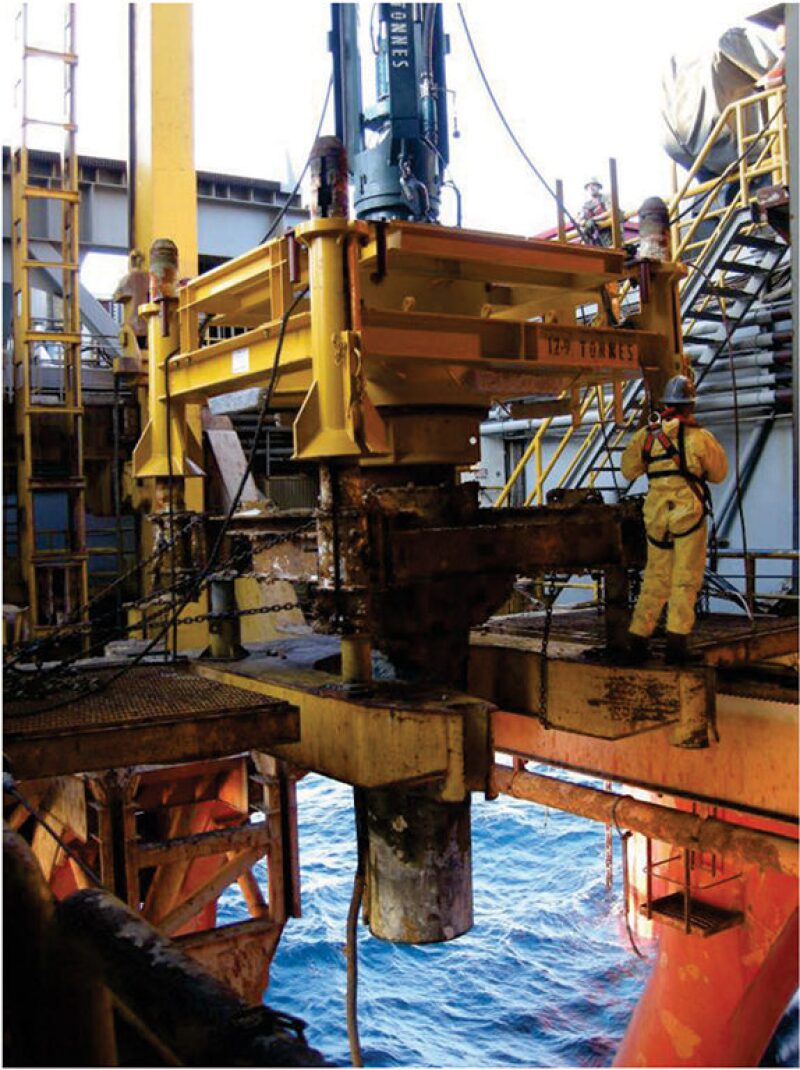
Phase 1 Abandonment Program. After a prerig remotely operated vehicle (ROV) program (detailed in the complete paper), Phase 1 consisted of the abandonment of the four simplest wells, which required wellhead removal and no BOP installation. The first two wells used a mechanical cutting system to sever the wellheads instead of the abrasive severance tool. This was because these wells did not have 9⅝-in. casing installed and, therefore, the cutting tool was more efficient for this well design. The abrasive severance tool was used in all wells that had 9⅝-in. casing installed because there was little confidence that the 9⅝-in. lock ring and packoff could be retrieved successfully, having been installed for up to 25 years. Fig. 1 shows the abrasive-cutting-tool assembly latched onto the recovered wellhead in the moonpool.
There were no significant issues with these abandonments other than the handling of the permanent-guide-base (PGB) -and-wellhead assembly and the temporary guide bases (TGBs) at surface. The PGB/wellhead assembly by itself was manageable but time-consuming. However, if the TGB was attached, and especially if it was filled with cement, the combined weight exceeded the rig’s designated safe-handling weight at surface of 50,000 lbm. In the event that the TGB could not be separated, the assembly would need to be wet-parked on the seabed for later recovery. This happened on the first well. Even when the TGBs were separate, they proved extremely difficult to handle at surface because of their size and shape. It took up to 24 hours of rig time to recover a TGB.
The main lesson from Phase 1 was to leave the TGBs and PGB/wellhead assemblies on the seabed to be recovered later by a construction vessel. Fig. 2 above shows a TGB (end view) as part of a PGB/TGB/wellhead assembly being recovered by the post-rig campaign, and demonstrates the significant size and handling difficulties involved.
Phase 2 Abandonment Program. There were a number of evolutionary program changes made during the campaign. Some were forced changes in response to circumstances, whereas others involved the implementation of improvement opportunities. The main changes are detailed in the complete paper. As the campaign progressed, a number of the nonroutine operations became routine and the later abandonments became operationally efficient.
The abrasive cutting of the 17 wellheads went extremely well, with a 100% success rate. The completion dual-bore riser worked as designed, and no issues were experienced with this equipment. The surface flow tree had ongoing issues with valve actuators sticking and seats occasionally passing; however, the rate of failure was manageable and service requirements were increased between wells to help mitigate the issues. The subsea equipment was wet-parked by releasing the hydraulic connector and letting the entity free fall 15 m to the seabed. This was required to protect the cutting tool that was stung through the wellhead assembly and the 30-in. conductor.
At the end of the abandonment program, there were 54 pieces of well-related subsea equipment, totaling approximately 500 t, wet-parked on the seabed. An ROV vessel was mobilized for field-decommissioning operations and was used for recovering the wellhead equipment.
Continual improvement was captured by an after-action-review process (please see the complete paper for details), in which lessons learned were captured after each major operation and were fed into the subsequent well.
This article, written by JPT Technology Editor Chris Carpenter, contains highlights of paper SPE 170523, “Abandonment of 19 Subsea Wells in the Jabiru and Challis Fields,” by Iain Clyne and Neil Jackson, PTTEP, prepared for the 2014 IADC/SPE Asia Pacific Drilling Technology Conference and Exhibition, Bangkok, Thailand, 25–27 August. The paper has not been peer reviewed.