
Learn, strategize, persevere, and optimize: In a nutshell, this was the message imparted in the eight sessions’ 24 presentations and the keynote luncheon speech at the SPE Liquids-Rich Basins Conference (LRBC), held 24–25 September in Fort Worth, Texas.
Conference presenters talked mainly about US basins and plays. However, this summary focuses on presentations that might also yield insight into onshore unconventional plays around the world.
Production Overabundance
With US natural gas production at well over 70 Bcf/D, Dave Pursell, research principal at Tudor, Pickering, Holt, & Company, asked “What do we do with all this gas?” (Fig. 1 above.)
He said natural gas liquids volumes are understated because producers are rejecting a lot of ethane and leaving it in the gas line. Ethane is used to make one of the world’s principal industrial chemicals, ethylene (also known as ethene). Ethylene is the most important organic chemical, by tonnage, that humans manufacture. It is a building block for a vast range of chemicals. Pursell thinks that the US might begin exporting ethane if prices improve.
He also said that, in the US, “gas is terrible. It’s always going to be terrible. LNG [liquefied natural gas] can’t come soon enough.”
A massive amount of processing and refining construction is under way along the US Gulf Coast, from Corpus Christi, Texas, to Mobile, Alabama, he said. But there is a labor shortage and a project backlog. In addition, projects are overbudget. Pursell points to high material costs and a lack of skilled labor as the primary roadblocks. “The peak oilers are right, the US has peaked—on conventionals—but they didn’t foresee the rise of unconventionals,” he said.
The Myth of Sweet Spot Exploration
“Sweet spot exploration is a destructive holdover from a ‘conventional’ mindset—that we want to drill the best possible location first,” said Bill Haskett, senior principal–energy strategy at Decision Strategies. “That tends to drive decisions, but it’s not good.”
Above all, said Haskett, “You have to have good rock. Nothing can save you if you don’t.”
In actuality, he said, with tight shales, “it’s only the top 10% to 20%—or maybe top quartile—that’s superior to your other wells. But most times we can’t predict coming in.” To just extrapolate from sweet spots, he said, “is statistically improper sampling and also impedes learning.”
Haskett said the best approach is to implement a pilot—but with the caveat that “A pilot needs to characterize the opportunity as a whole. It should not attempt to high-grade the area of potential.”
He described the purpose of a pilot as “to determine with an acceptable level of confidence that what you have is at least as much as what you need to have in order to create/sustain a viable project. Precision is unwarranted.”
A fair pilot, Haskett said, “must reasonably sample the area to be developed. To increase value confidence, the pilot must describe the full distribution. Well density will depend on scale, rate of change across the acreage, offsetting pertinent tests, and thresholds.”
The exception to these would be only where the sweet spot area itself provides a material play extent that is both large enough to be able to contribute completion and production learning and large enough to be able to apply what is learned in order to deliver profit.
There are six “simple rules for value in unconventionals,” according to Haskett:
- Enter with a purpose; sample fairly.
- Embrace uncertainty: You only know what you know.
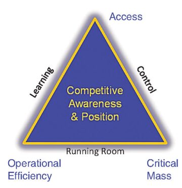
- Seek to understand your material interest in material plays (Fig. 2).
- Create and maintain your real competitive advantage.
- Have an exit plan, but don’t give up too early.
“We don’t create plays out of sweet spots,” Haskett emphasized. “Sweet spots are the bonus you get once you enter and have been there awhile.”
Data Drives Development Plan Optimization
Laredo Petroleum’s acreage—located in the Garden City area in the heart of the Permian Basin’s Midland basin—presents many characteristics that help drive efficiencies. Karen Chandler, director operations, technology, and planning at Laredo, in her keynote presentation at a special LRBC luncheon held 25 September, spoke about how the company is optimizing its acreage development plan.
Founded in 2006, Laredo drilled its first horizontal well in 2009, and went public in 2011. Currently with around 400 employees, the company has 154,374 de-risked net acres (approximately 396,000 net effective acreage), focused on the upper, middle, and lower Wolfcamp, and the Cline. Average working interest the company holds in their acreage is around 88%, with approximately 66% held by production.
Laredo acreage is situated in a swath that extends primarily through Reagan and Glasscock counties, Texas, over the thickest column of productive sediment—about 2,000-ft thickness of play. The challenge is to optimize planning for each zone in each well so that each well produces the maximum amount of resource.
With an inventory of tests from more than 875 vertical wells, mining this data is what drives Laredo’s development plan optimization. According to Chandler, the company has many data sources—14 whole logs (around 3,700 ft total); 54 single-zone tests; more than 8,000 cumulative openhole logs; 100% gravity/magnetic data coverage and interpretation; 838 sq miles of 3D seismic, giving 95% coverage of Garden City acreage; 21 microseismic surveys (operated and nonoperated); and 37 production logs.
This large amount of significant data confirms the quality of Laredo’s acreage. More than 3,700 horizontal locations have been identified for development in the four zones noted above. The company anticipates around 50 years of drilling inventory at their current pace.
“Data drives development plan optimization,” said Chandler. Laredo does a lot of experimenting in the field and thoroughly analyzes the results. More than 70 reservoir attributes are evaluated to determine which have the most impact on optimal results.
The company’s aim is to leverage Laredo’s resource concentration and contiguous acreage base to facilitate efficient development of the entire resource. “Stacked laterals on multi-well pads optimize multizone development,” said Chandler. “This becomes a kind of ‘manufacturing’ process giving top-tier well results in multiple horizons.”
Studying Depletion Behavior to Understand Completions
Basak Kurtoglu of Marathon Oil spoke about how well completions and fracture interference affect well performance. In a study she conducted, she looked at a number of parameters, such as well spacing, in the company’s Eagle Ford acreage and then performed production data analysis using diagnostic plots to see if reservoir connectivity was working or not working.
She studied depletion behavior with 80-acre, 60-acre, and 40-acre spacing. Kurtoglu said it was difficult to draw conclusions. “Whatever you do is not enough. With fracture interference,” she said, “you’ll impact other wells. You might optimize for one well but affect others in the future in unknown ways. Worst case is you get things like deferred or lost production or plugging.”
There was a “stack-and-frac” pilot, with multi-horizon development. Stage opening was lowered from 400 ft to 175 ft. According to Kurtoglu, the improvement in completion efficiency is helping offset the impact from tighter acre spacing. The resulting increase in production comes at a cost, but production nonetheless is much better. She said, “We’re trying to understand what the data are telling us—trying to develop a benchmark.”
Solving Lift Issues Using Root Cause Analysis
Josh Woods, production engineer at Anadarko, examined the company’s use of rod pumping on their Delaware basin acreage—exploiting zones such as the Bone Spring, Wolfcamp, Strawn, Atoka, and Avalon. Baseline normality was one intervention (rod pump failure) per year. “There are significant flow and lifespan issues with rod pumping,” he said. Nonetheless, the company uses rod pumping the most on this acreage.
The company decided to introduce an intermediate form of lift, electrical submersible pumps (ESPs), to see if using an ESP for a while following initial free flow, then placing the well on rod pumping, might result in higher economic ultimate returns than proceeding directly from free flow to rod pumping. Failures were identified and examined using a process called root cause analysis. Woods and his colleagues did not simply want to know what happened and where; they primarily wanted to know why.
The rod pumping strategy Woods and his group came up with is a circular process with four stages that begin after well intervention—and lead again to well intervention should another failure occur:
1. Identify Root Causes
- Compile a database of the type, location, etc. of failure
- Collect samples such as pumps that break down, solids, tubing, and rods
- Review with dynamometer cards
- Focus on “why,” not “what”
2. Optimize Design
- Pump specifications
- Rod string
- Bottomhole assembly
- Accessories
- Chemical treatment(s)
- Keep asking: “Do the design changes address the root causes of failures?”
3. Ensure Proper Installation
- Care/handling of equipment
- Unit alignment
- Downhole pump spacing
- Proper tool usage
- Detailed documentation
- Do your installation procedures ensure the integrity of your design and components?
4. Measure and Monitor (Fig. 3)
- Production surveillance tools
- Operator observation/upkeep
- Dynamometer card analysis
- Can your monitoring techniques measure the design effectiveness?

The first root cause of failure Woods and his group found was mechanical wear. They identified the reasons on the basis of side-loading prediction indicated in design software, rod examination, and the condition of the tubing. Their solution was to use a differently designed rod pump that operated at a much slower speed, with a longer stroke and a rod rotator. They also upsized from 2.441-in.-ID bare tubing to 2.67-in.-ID lined tubing, thus transferring deflection uphole. Woods said positive results so far have been obtained by running 3.5-in.-OD lined tubing on the bottom 2,000 ft to prevent ID restriction and protect the most common hole-in-tubing locations.
Corrosion, which was much more prevalent than they thought, was another significant root cause of failure. Woods and his colleagues did a tubing scan and tubing sample analysis and found corrosive solids present in the pump. The design changes they implemented were to treat kill fluid with biocide to kill organisms, modify the chemical program, and use a corrosion inhibitor to coat the pipe.
Another root cause was pump friction, which could be seen by analyzing the dynamometer card, checking pump integrity and location of failure, and finding the presence of solids in the barrel. In optimizing design, they increased plunger clearance, installed a hollow valve rod and guided pony rod, and optimized the chemical program.
But by far the biggest problem Woods and his group discovered was improper installation. They found the source of that problem was too much metal-to-metal contact during pipe handling. So they devised polyvinyl chloride covers for pipe stacks; used a spreader bar for fork lifting; and ensured pipes are properly spaced, rods are made up correctly, and that the polished rod is properly aligned; that rods are torqued up properly; and that proper handling and usage of tools/equipment occurs while pulling out of hole or running in hole.
Woods and his group are pushing the limits of rod pumping and maximizing drawdown. They are asking: How large can pumps and rod units go? They are looking at ESP again. And they are really interested in gas lift.
The key points Woods and his colleagues found were the following:
- Intervention rate impacts the following:
- Oil volume deferment
- Lease operating expenses
- The number of required staff and vendors
- Root cause analysis should drive design changes.
- Proper design may not mean proper installation—so they are developing recommended practices.
- Improved surveillance techniques allow for recognition of operational deficiencies.
- Rod pumping system should be designed to maximize well production potential.
- Above all, the design workflow can always be improved and further optimized.
Conducting Thorough ESP Testing
Apache’s Sean Murray, production engineer, and Ray Nichols, ESP specialist, thoroughly tested the ESPs of several manufacturers, including Borets, GE, Schlumberger, Baker Hughes, and Halliburton. With ESPs, the major issue is gas production—how the ESP handles the flow of gas and sending it up to the surface.
Their tests indicated that the best solution was a pump that separated the gas and had a downhole compressor that sent the compressed gas to the surface. The key is the downhole gas separation step, then downhole compression. This means the pump does not directly have to handle the actual flow of the gas through it and up to the surface. This pump improved drawdown, increased rates, reduced gas locking, improved recovery, reduced the number of failures, and resulted in less downtime.
The presenters are also looking to the future to see what will happen when they use horizontal ESPs—and they are already examining various options. Murray said, “We haven’t tried gas lift. Too many problems. We don’t have the infrastructure to handle the gas [e.g., to separate, compress, store, and pipe it]. Besides, the paraffin content in the gas is high, so there’d be clean-up issues.”
Exploring Fracturing Pump Reliability
Blake Burnette, director equipment R&D at Baker Hughes Pressure Pumping, discussed issues regarding the reliability of fracturing equipment—focusing in particular on fracturing pumps.
He did a study for his company comparing fracturing pumps’ advertised hours of operation versus real hours of operation. “When a problem is really confusing, it’s more than one problem,” he said. He mentioned several fracturing pump problems: wash out due to deep grooves that had cut into the steel; cross-bore; pulsation dampening; supercharge pressure; losing prime (due to the introduction of air); sanding off hoses, resulting in low viscosity fluid and rate slowdown; overall design issues affecting incremental horsepower, the discharge canal, and valves; and the effects of gravity.
Essentially, Burnette said, “fracturing pumps haven’t changed design since they were introduced in the 1920s. It’s the same design pump, with scaled-up horsepower; and you reach a limit of how much weight you can have. And valves haven’t changed over the years.”
The greatest enemies of fracturing pump equipment, according to Burnette, are sand erosion/abrasion; dust and dirt; corrosion from salt and fumes (acid being more corrosive to equipment than salt); equipment abuse; vibration; pressure washer; and bad roads.
He examined torsional stresses over time. When he switched from water to viscous gel, the gel was harder to get through the valves. He examined why.
The cost of down pumping equipment is USD 20,000 to USD 50,000/day per truck. The cost of a failure during the fracture job can involve several consequences: The job gets cut short, personal injury can happen, and well integrity can be compromised.
Burnette then proceeded to talk about safety issues and who ultimately bears the cost when there are fracturing pump problems. One can prevent pump problems by identifying and resolving issues before they happen, including safety issues; reliability issues; equipment complexity issues, by making the equipment so simple to operate that you eliminate the need for training and reduce manpower requirements; and avoiding opportunities for issues to arise by reducing rig-up time.
Fit-for-Purpose Artificial Lift
Amber Blakely, production engineer at Anadarko, talked about using fit-for-purpose artificial lift in the Powder River basin. Her basic artificial lift concept is “Optimization may not mean standardization.” Her philosophy is to look at each well individually, that methods are not interchangeable, and that multiple forms of lift should be considered and evaluated. The best will be based on your goals—what you want to achieve. She emphasized that lift should be anticipated before drilling: “This is the way you understand ‘full value-chain economics.’”
Blakely took into consideration the physical wellbore data and also production data. The development strategy would be different for jet pumping, plunger lift, rod pumping, or ESP. There is not an application for gas lift for their acreage.
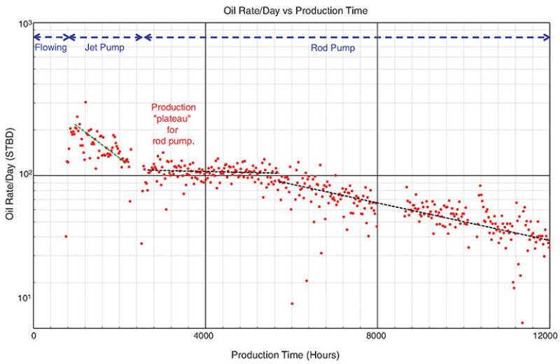
In one example she gave, an exploration well was flowing and the goal was to draw down the well quickly. So they installed a jet pump and were able to see high levels of production (Fig. 4). After 2 months, they switched to rod pumping.
In a second example, they used an ESP at first, then moved to rod pumping. This also boosted initial production rates. In the third example, they went directly to rod pumping.
In a fourth example, they evaluated the well for jet pumping. Blakely said, “It’s pumped to a higher rate than could be achieved with rod pumping, with an incremental increase in oil revenue of around USD 5.5 million.” She said they will put on rod pumping when the well is no longer producing at the higher rates that rod pumping cannot handle.
With the fifth example, they examined the issue of high side-loading. So they designed against that issue using rod pumping. They used a slow-stroke unit—at 3½ to 4 strokes per minute. “Less cycle means less wear,” Blakely said.
“Don’t be afraid of using two methods,” she added. “Intermediate lift can create value. Install and optimize.” She learned from the data that jet pumps are an effective low-risk tool. But rod pumps are inevitable—and they are reliable and very versatile.
At the end of her presentation, she posed a challenge: “Next year, I’d love to see actual data and run lives for running artificial lift in laterals.”