
In artificial-lift applications, a new anchoring device for insertable progressing-cavity pumps (I-PCPs) extends I-PCP applications to a larger set of candidate wells. The I-PCP anchor allows an I-PCP to be run, landed, operated, and removed from a tubing string in the absence of a previously installed pump-seating nipple (PSN) typically required for installation.
Conventional PCPs are installed by running the stator assembly on the bottom of the tubing string and the rotor on the bottom of the rod string. In contrast, with an I-PCP, the entire pump assembly is installed by the rod string and landed inside the tubing string. This allows the pump to be pulled and rerun by the rod string. The primary advantage of this system is the elimination of costly and time-consuming tubing pulls to change worn or damaged pumps or to switch to different pump sizes and configurations as downhole pumping requirements change.
I-PCPs are conventionally installed with a PSN in the tubing string and a corresponding set of seating rings in the pump assembly. While this method provides a reliable method of landing, it also requires that the PSN be originally installed and it limits the positioning of the pump to the associated pump-seating location.
Weatherford’s Flexisert I-PCP anchor is an installation method that does not require a PSN to be in place. The impetus for the anchor’s development was the recompletion of depleted offshore gas lift wells to PCP systems. The anchor makes this possible because it allows the gas lift system to be left in place while inserting the new anchor.
In general application, the I-PCP anchor allows I-PCPs to be run in wells that are not equipped with a PSN, or where the PSN is at the wrong location or has specifications that are unknown. The anchor system also provides an artificial-lift option to reactivate old wells without pulling the tubing.
The anchor reduces the downtime and costs for replacing different forms of artificial lift, including eliminating the need to pull and rerun production tubing if a PSN is not already in place. It is deployed in one trip to provide a seal and prevent rotation and axial movement. In current markets, the smaller rig requirement seen from running rods rather than tubing reduces wait time, which limits production losses.
Technical Details
The anchor is manufactured in 2⅞- and 3½-in. production-tubing sizes and is able to pass through common tubing restrictions, depending on the internal diameter of features such as PSNs and subsurface safety valves.
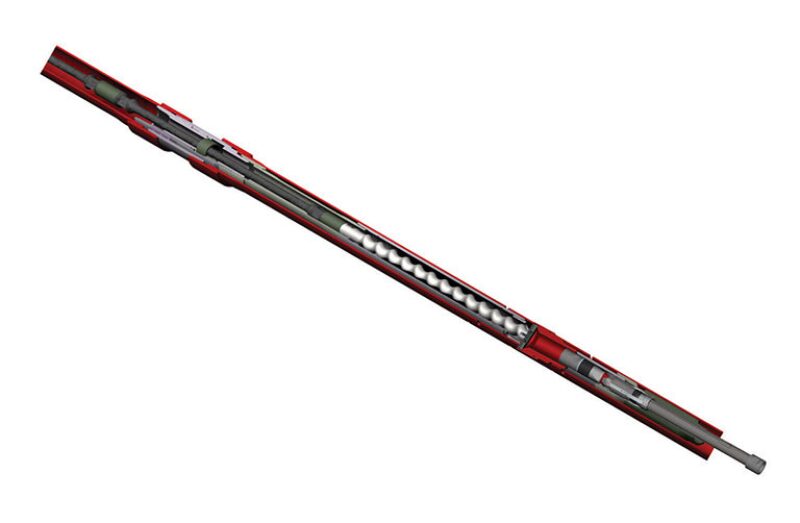
The devices are designed to prevent movement and provide sealing between the high-pressure discharge end of the pump and the lower wellbore. The main components consist of a PCP adapter head, a bladder, a slip cone, bidirectional jaws, a shear screw, a slip assembly, and a mandrel body with J-slot grooves (Fig. 1). Tool specifications for each size address a full range of torque, downward and upward axial loads, and differential pressures associated with common insert-pump configurations.
The anchor is run on the bottom of the I-PCP and deployed by lowering it to the target position, lifting up to the setting position through a J-slot, and setting down with full rod weight to engage the ratchet ring, slips, and bladder.
Removal is achieved by pulling the rod string upward to shear the anchor pins and release the ratchet, slips, and bladder. Once at surface, the tool is inspected, redressed, and rerun.
Applications
Target applications are artificial-lift wells where an I-PCP cannot be installed because of a lack of a PSN; where another form of artificial lift has failed; and/or where changes in pump-setting depth, pump volume, and lift are required. In applications where there is high sand production or paraffins, I-PCP-anchor use should be reviewed carefully because of the system’s narrow pump/tubing annulus. Horizontal or highly deviated applications also should be evaluated to ensure that rod weight is sufficient to engage the tool.
Ongoing field trials include applications in Oman, Venezuela, and Mexico. Six field trials have resulted in four successful installations. The other two were compromised because of dirty tubing/temperature differential issues, and a lack of PSN depth information.
In Oman, a 3½-in. anchor was installed onshore in a vertical well, and it had been operating for more than 500 days at the time of this writing. The installation changed out a conventional PCP for I-PCP equipment and left the conventional stator in the well. Intervention time with the conventional PCP was 72 hours, while intervention time with the I-PCP-anchor system was 18 hours, for a 75% reduction. Oil production remained the same, with 85% water cut and a trace of sand.
In Venezuela, a 2⅞-in. anchor was installed onshore in a vertical well; that I-PCP system had been operating for more than 330 days at the time of this writing. Production was maintained at the previous rate, with a 4% water cut and no sand.
Tubing had been pulled previously from the well, which had been produced with conventional PCPs. The rotor was partially inserted while running the anchor because of previously identified restrictions in the tubing. The anchor was set prematurely high, which prevented installation of surface equipment. One joint of tubing was removed, and one sucker rod was removed and replaced with pony rods, allowing the anchor to be set at the target depth.
To accommodate early anchor setting, it was recommended that the polished rod length be slightly longer than rotor length, and that the installed pony rods be equivalent to the length of the polished rod. The configuration maintains the ability to flush the well. The installation also accelerated development of a method to lock the rotor for installation and ensure that it is inserted fully into the stator.
In Mexico, a 2⅞-in. anchor was installed onshore in a deviated well and the I-PCP system operated for 92 days before failure because of a break in the stator tube unrelated to the anchor (Fig. 2 above). The lift system was installed successfully in a completion designed to mitigate gas production. Free-flow production was doubled with 2% water cut and no sand. Again, the rotor was partially inserted in the stator when running the anchor, and it was set prematurely high. On the basis of lessons learned, the multiple pony-rod string design allowed for removal of pony rods.
The four successful field trials to date have met technical and functional requirements. The space-out/anchor-setting issue experienced in two of the trials resulted in development of a rotor-lock mechanism. Reasons for anchor failure include improper installation, improper review of application, introduction into a wrong application, overtorque, and dirty tubing.
Discussion and Next Steps
Changes resulting from testing and field trials include revising the J-slot to confirm that the tool will “J over.” A patent-pending rotor-locking feature was added to the anchor to confirm that the rotor placement is known when the pump is spaced out (Fig. 3). Pump space-out procedures were developed to provide the option of a flushing operation.

The anchor currently in field trials is now considered a commercial product with a prior review needed to confirm its applicability. Future field trials include installations in India, where four applications introduce the new rotor-lock system, and in Australia. Future development plans include an I-PCP-anchor model for 4½-in. tubing.
Editor’s note: If you have a new technology introduced fewer than 2 years ago and would like to highlight it in Young Technology Showcase, please contact JPT Technology Editor Chris Carpenter at ccarpenter@spe.org.