Safety, efficiency, and accuracy are fundamental goals of well construction. But as the search for new oil and gas resources pushes into deeper waters and increasingly complex reservoirs, meeting these goals has become more challenging.
A better understanding of the subsurface is one of the most efficient ways to mitigate drilling risk and optimize operations’ performances. The ability to map the reservoir in real time, while drilling, contributes to step change, such as understanding sweep efficiency in horizontal wells, landing and maximizing the length of drain within the optimal zone of the reservoir, and avoiding time-consuming sidetracks or pilot holes.
While the industry has several bed-boundary mapping tools and services to delineate the reservoir as a well is drilled, their depth of investigation is limited. The best of these systems can map to a distance of 15 to 20 ft (4.6 to 6.1 m) from the borehole. These limitations have made it difficult to improve directional drilling within narrow pay zones or complex reservoirs containing faults, unconformities, and injected or channel sands. As a result, wellbore positioning may be suboptimal and drilling may be less efficient.
Real-Time Reservoir Mapping
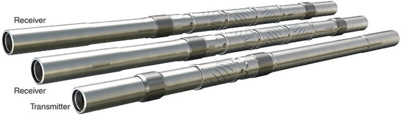
Schlumberger’s GeoSphere reservoir mapping-while-drilling technology was developed to improve the operator’s understanding of the reservoir beyond the first few feet from the wellbore. The system employs an array of multiple subs in the bottomhole assembly to transmit deep directional resistivity measurements that map multiple reservoir layers with resistivity contrasts in real time (Fig. 1). The multispaced receiver array extends the radial depth of investigation to 100 ft (30 m) from the tool, revealing subsurface bedding and fluid-contact details at a true reservoir scale.
The significant improvement in depth of investigation provides a reservoir-scale view, enabling operators to optimize landing, reduce drilling risk, and maximize reservoir exposure. By integrating real-time reservoir maps with seismic surveys, the interpretation of reservoir structure and geometry can be confirmed and refined, enabling a step transformation of field development strategy.
The system provides a wealth of real-time reservoir knowledge that improves well construction by helping the operator accurately land a well in its target zone and steer the drill bit to keep the wellbore away from reservoir boundaries, dips, and fluid contacts. The real-time mapping data obtained also helps the operator refine the structural and geological reservoir models, thus optimizing plans for recovery and improving development strategies for the entire field.
A Smooth Landing
The ability to land the wellbore accurately into the reservoir’s target zone of interest is a critical first step in delivering a well that achieves its long-term production potential. Although pilot holes may provide good local information about the reservoir geology, they are often ineffective in predicting lateral geological variability—a critical factor when drilling into long horizontal pay zones. Similarly, well-to-well correlation alone cannot accommodate various structural shifts inherent in many downhole environments.
The reservoir mapping-while-drilling technology’s extended depth of investigation, which is enabled by deep directional electromagnetic measurements, helps mitigate the risk of shallow or deep landings. The system supports the identification of large- or local-scale depth shift of the reservoir, providing a precise localization in true vertical depth (TVD) of the top of the reservoir and thus eliminating the cost of drilling a pilot hole. By providing a clear, real-time view of formation boundaries and fluid contacts, the system also avoids the risk of losing lateral exposure and creating sumps.
An offshore operator in Australia used the technology to help define reservoir boundaries ahead of entering the target section of its reservoir. While pilot-hole information confirmed the presence of the reservoir and identified a structure near the entry point, the location of the reservoir top could not be accurately estimated solely from the pilot hole or from other offset wells.
The operator needed to map the top of the reservoir and determine fluid contact levels to optimize landing and maximize reservoir exposure. The task was challenged by seismic uncertainty of plus or minus 33 ft (±10 m) TVD that severely affected structural control, the reservoir boundary knowledge needed to enable optimal hole positioning. To land the well as closely as possible to the reservoir cap and achieve optimal reservoir exposure of at least 30 ft TVD from the oil/water contact (OWC) boundary, the reservoir mapping-while-drilling technology was deployed.
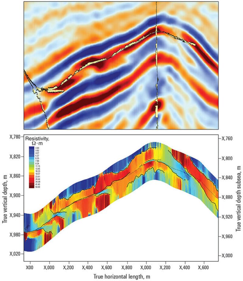
Upon exiting the casing shoe, the system mapped the top of the reservoir at 20 ft (6 m) TVD below the well path, and located the OWC at 43 ft (13 m) TVD below the reservoir top. The real-time mapping of the reservoir and OWC before entry facilitated an optimal landing at an ideal standoff and angle relative to the overburden. In addition, the reservoir data provided by the technology was integrated into the operator’s 3D static geological model, which helped update and optimize future drilling and field development plans (Fig. 2).
Staying in the Zone
Once in the target zone, the operations team uses the technology’s real-time mapping data to avoid undesired exits into nonproductive layers. By revealing details of the reservoir structure and fluid boundaries up to 100 ft from the wellbore, which significantly exceeds the formation coverage of conventional logging-while-drilling tools, the system helps the operator avoid geological sidetracks and hazards in complex formations. This allows the operator to adjust drilling trajectories well ahead of anticipated variations, such as water zones and disconnected sand bodies. Thus, a smoother wellbore can be drilled, resulting in a well that is easier to complete and has a smoother production profile.
The mapping data is also combined with surface seismic interpretation to extend the amount of zonal coverage. This enables geoscientists and drilling engineers to extend laterals, even in complex geological settings, within the sweet spot.
This system’s ability to keep the drill bit in the pay zone with greater accuracy was a particular benefit for a North Sea operator who was attempting to steer two production wells within target reservoir sands, while avoiding the unstable shale cap and maintaining desired OWC standoff. The target reservoir, a glauconite-rich sandstone, was 7 to 16 ft (2 to 5 m) thick and consisted of post-depositional remobilized sand (injectites). The nature of the reservoir, coupled with its low resistivity, created a problem for conventional reservoir steering methods and traditional bed-boundary mapping tools, because they could provide a depth of investigation of only 7 ft or less.
The combined contribution of the reservoir mapping technology’s extended depth of investigation and the results from a surface seismic survey made it possible to steer ahead of reservoir structure shifts. Both horizontal wells were placed within the thin reservoir, away from unstable shale, and drilled completely in zone to target depth.
The first well was drilled in a single run, achieving a horizontal section of 2,674 ft (815 m) in measured depth (MD) with a net-to-gross ratio of 0.98. Actual reservoir exposure exceeded planned exposure by 213 ft (65 m), and the tortuosity of the well was kept within requirements. The second well was also drilled in one run, achieving 853 ft (260 m) MD with a 0.96 net-to-gross ratio.
The two horizontal wells were steered optimally in the reservoir, 96% in zone, with no sidetracks. Both wells were tested above expectation at up to 8,000 B/D with minimal drawdown. The operator’s understanding of the reservoir’s heterogeneity was also greatly improved. The information from the reservoir mapping system was considered critical in refining the reservoir model.
Mapping Ideal Field Strategy
By delineating subsurface beddings and fluid contacts at the reservoir scale, the technology enables operators to optimize field development strategies. Real-time mapping data of reservoir geometry and lateral heterogeneities can be combined with surface seismic data to refine structural and geological models and afford a better understanding of sweep efficiencies in horizontal wells, resulting in enhanced production and recovery.
An operator drilling tight-gas production wells offshore southeastern Australia faced several challenges in its attempt to reduce reservoir uncertainty and improve drilling efficiency. This field has a complex stratigraphy, presenting an anticline structure, and is composed of discontinuous sand bodies with siltstones layered between them.
Developing this asset would require the operator to drill long horizontal wells to expose the wellbore to as many of the sand bodies as possible, thereby creating a tortuous and complex wellbore. The operator also faced significant seismic uncertainty of tens of feet (±10 m).
Taken together, these challenges precluded the use of conventional methods to map the reservoir, optimally position the drain trajectory, and make real-time steering decisions to connect the sand bodies. Additionally, the operator wanted to avoid the need to drill a sidetrack well, which is costly and mechanically risky.
The operator selected the reservoir mapping-while-drilling technology to map the complex reservoir. The system successfully mapped remote sand bodies at distances exceeding 115 ft (35 m) TVD, bridging the gap between near-wellbore scale measurements and surface seismic measurements at the reservoir scale. The distance-to-boundary evaluation enabled real-time updates of the seismic interpretation model, which helped to increase the understanding of the geological picture.
As a result, the operator was able to steer the wellbore aggressively to connect the discontinuous sand bodies, thus maximizing reservoir exposure. The well trajectory built from 84° to 107° before turning and dropping at the crest of the structure to maintain maximum reservoir exposure. The wellbore was kept completely within the reservoir, with no need to drill a sidetrack well. The operator projected that without the use of this technology, a costly and risky sidetrack likely would have been necessary.
Advancing Production
The mapping data enabled by the technology can be integrated into an operator’s 3D reservoir models to optimize the drilling operations and completion designs of a current well and to optimize production improvements and long-term field development strategies. For example, reservoir maps from the real-time mapping system can be seamlessly exported into exploration and production software platforms, whereby experts can create 3D displays with formation evaluation data attributes to enhance the evaluation of layered formations.
Operators have already integrated the mapping data into their best practices to refine completion design, regulate flow control management, and enhance depletion profiles before completions are run. Indications of fluid contacts enable injection and production well optimization by influencing infill drilling decisions so that potential pay zones will not be bypassed.
The reservoir mapping-while-drilling technology has been successfully tested in more than 150 field operations in the North Sea, Europe, Russia, North America, South America, Australia, and the Middle East.