Dynamic underbalanced (DUB) perforating is a process that creates a negative pressure differential, or underbalance, causing fluid to move toward the wellbore even in an initial overbalanced static condition. A DUB condition can be controlled by understanding and carefully managing the temporal pressure transients by use of multiple methods within the wellbore during and after gun-system detonation. Recently, a series of instrumented perforation experiments demonstrated that existing cleanup models do not accurately predict perforation cleanup when perforating in a DUB condition.
Introduction
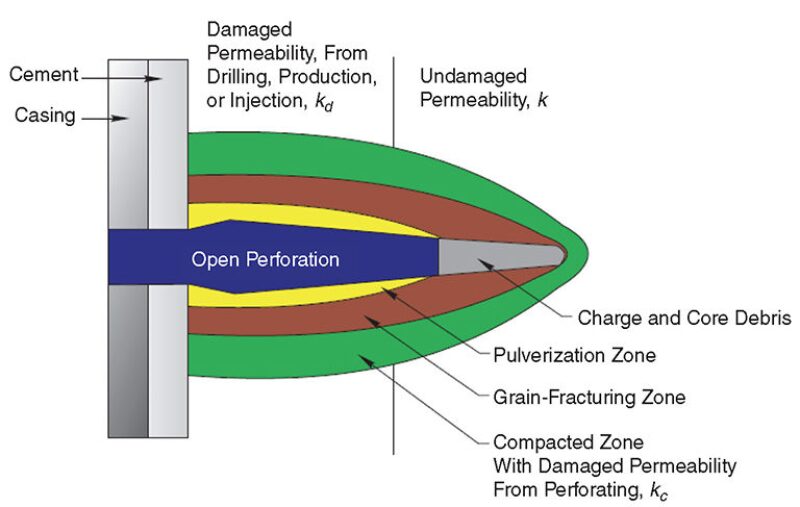
Underbalanced perforating methods have been applied successfully since the 1950s, shooting both wireline and tubing-conveyed perforating guns. As shaped-charge jet-perforator systems became more advanced, using powdered metal liners, performance steadily improved. The art of minimizing the compacted and damaged area surrounding the perforation tunnel, commonly known as the crushed zone (Fig. 1), began shortly afterward. Much of the initial work involved shooting charges into prepared Berea sandstone cores while documenting the effect of a differential pressure toward the wellbore upon perforation efficiencies. As the benefits of an underbalanced pressure differential were observed, extensive testing established criteria for flow volumes and differential pressures required to remove or minimize the crushed zone created during the perforating event. Specifically documented was the role of trapped atmospheric pressure inside a perforating gun surrounding the shaped charge and components, known as free gun volume (FGV), which enabled the formation pressure to act as a differential and expel charge and crushed formation into the gun.
As perforating research and field observations continued, a series of widely used and accepted formulas was established to document the magnitude of differential pressure required to ensure cleaned perforation tunnels. This paper reviews the effectiveness of each of these models, originally developed for a static underbalanced condition before perforating, to predict cleaning and removal of the crushed zone in a series of tests with a dynamic pressure differential. The test series uses an advanced perforation-flow laboratory to detonate an 11.1-g deep-penetrating shaped charge. Each charge will perforate a 24-in.-long, 7-in.-diameter Berea sandstone core with 3,950-psi applied pore pressure; 9,950-psi simulated overburden stress; and 4,900-psi wellbore pressure, creating a static 950-psi overbalance. Although the initial static condition will be overbalanced, a DUB condition will be established by wellbore and pore fluids filling the FGV upon detonation.
Testing Apparatus
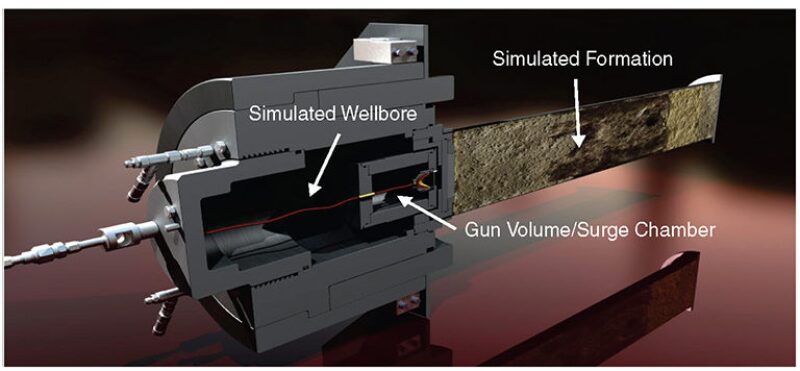
The testing apparatus used to simulate downhole perforating conditions for this work is an advanced perforation-flow laboratory at the Jet Research Center, which is modeled after an API 19B Section IV test-vessel apparatus (Fig. 2). The test setup uses a simulated gun module that contains a single shaped charge, a detonating cord, and a sufficient amount of FGV that can be regulated relative to the actual gun system being evaluated. FGV for an API 19B Section II or IV test can be calculated by determining the total system FGV and dividing by the total number of charges, thus providing the FGV on a per-charge basis. The FGV can be increased to simulate the downloading of a gun system, the incorporation of surge chambers, or a variety of other methods. The gun module is set inside a simulated wellbore volume. After detonation, the shaped charge penetrates the gun module simulating the gun scallop; crosses a defined clearance between the gun and casing wall through the pressurized wellbore fluid; and then penetrates the casing wall, cement, and finally the pressurized target rock.
The FGV within the simulated gun module can be modified by using inert material, such as shatter-resistant steel bearings. These can be placed inside the void space around the shaped charge to match the specific FGV relative to the system used downhole.
Rock cores used are dried to constant mass at 200°F and then vacuum saturated in odorless mineral spirits, enabling the gravimetric porosity value to be calculated. Each core is then mounted in the pressure vessel in which the overburden pressure is applied, and steady-state flow through the core is achieved to determine permeability.
High-speed pressure sensors, capable of sampling at 115,000 data points per second, are attached to the simulated wellbore to measure the wellbore pressure response during and immediately after detonation. The result is a profile of the transient pressure in the wellbore during the perforating event, capturing the inherent or engineered DUB condition if created.
Laboratory Testing
An extensive testing program was conducted to evaluate the effect of FGV on creating a DUB condition and the cleanup of perforation tunnels. Observations were made to determine whether established models for static underbalance could predict perforation cleanup when only a DUB condition is achieved. Fig. 3 presents a comparison of two test shots from the series, each with different FGV. As expected, the greater FGV created a larger DUB condition. Core 09 was perforated using 241 cm3 of FGV, creating a maximum dynamic underbalance of 2,280 psi, which resulted in only 3.30 in. of open perforation tunnel or 38% of total-core penetration. Core 11 was perforated using 905 cm3 of FGV, creating a maximum dynamic underbalance of 2,590 psi, which resulted in 8.10 in. of open perforation tunnel or 100% of total-core penetration. Immediately after the perforation tunnel is created, the surrounding wellbore fluids enter the perforation tunnel in an attempt to equalize the wellbore and pore pressures (overbalanced condition). However, the wellbore pressure decreases beyond the pore pressure, thus establishing an underbalanced pressure differential where one did not exist initially—a classic example of the DUB condition.
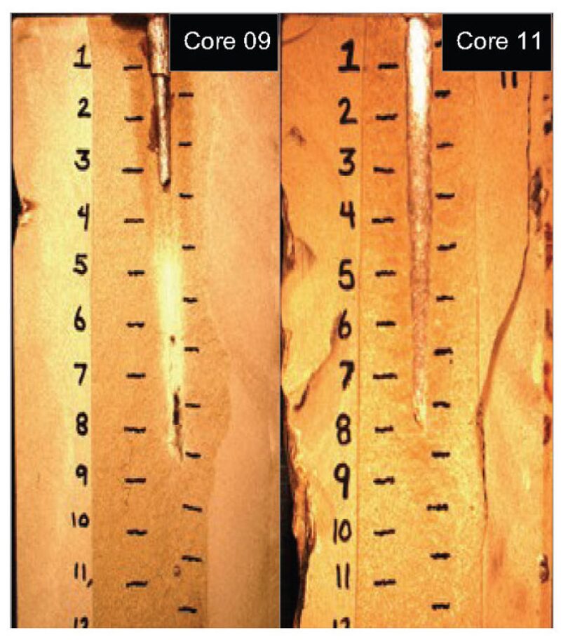
Although Cores 09 and 11 were exposed to an underbalanced pressure greater than the minimum required by the presented models to achieve a clean perforation tunnel, only Core 11 was cleaned sufficiently. Core 09 was exposed to a 2,280-psi underbalance and was cleaned only partially. Fig. 5 in the complete paper shows that the maximum underbalance for Core 09 lasted for a much shorter period of time than that for Core 11, suggesting that there is a time dependence to achieve cleanup not considered in the models evaluated. The resulting DUB effect is related directly to the amount of the FGV increase in the simulated perforating gun in the experimental data.
Discussion
In a perforation event, a charge punches a hole from the gun into water, through casing, then into rock. This action is followed by a bubble of explosive mixed with water, air, and other materials gathered along the way. The charge creates a perforation tunnel filled mostly with explosive gas. This gas, along with the liner, compresses the material on the tunnel boundary. Because the pressure in the perforation cavity is high, flow does not occur until the gas relaxes in pressure. Gun volume plays a role in the relaxation. The bubble then escapes the tunnel. This gas rush precedes any underbalance effects and will begin the underbalance process as soon as the gas pressure is below the pore pressure. Because the gun is already at high explosive pressure, the bubble of explosive gases will flow into the region between casing and gun or into the gun if the pressure is relaxed quickly enough. As the cavity clears, the pressure underbalance forces pore fluid to migrate rapidly to the wellbore. The first region to experience the effects of the low-pressure wellbore fluid is near the perforation-tunnel entrance.
Removal comes from two mechanisms. The first involves the flow through the crushed zone that then entrains and removes lower-porosity particles. The second mechanism entails the tip eroding away and then flow along the cavity erodes material off the walls. These two mechanisms can occur at the same time. The tip effect would benefit from a rough cavity wall. The uniform case is less sensitive to the rough cavity wall, but the uniform case is more sensitive to particle size in the crushed zone. The first region to experience the underbalance is near the tunnel entrance; consequently, cleanup can, in principle, occur at both ends of the cavity: at the throat as a result of an early start and at the tip as a result of the weaker crushed zone.
Previous work has focused on solving the pressure equation and then populating a flow equation, such as the Darcy equation. A rock-strength threshold was used. First, the layer crushed-zone thickness is estimated for an 11.1-g deep-penetrating charge by shooting into a standard quality control setup with dry sand as the target. The result showed a high-density region around the tunnel cavity of 0.2 to 0.5 cm. This result correlated with physical measurements made of the perforated cores. A thin layer of material is assumed along the conical structure. A slab model is initially assumed, but the model can be extended to a cylinder if necessary. Next, it is assumed that the flow moves a boundary of material, which in turn alters the pressure gradient.
As the flow increases, instabilities break up the flow; these instabilities transition to eddies, which in turn transition to smaller eddies. This is the so-called cascade to smaller scales. Using a tensile strength of 600 psi, the cleanup occurs quickly, starting at flows of 200 cm/s. The crushed zone is separated from the tunnel wall in approximately 300 microseconds, and the flow pushes the now-free material out of the perforation cavity in roughly a few milliseconds.
Now, consider the case of the tip. In this case, the tip of the perforation tunnel has the lowest tensile strength. The flow then can predominate along the length of the perforation tunnel. This flow would clear the crushed material by friction at the surface. This is a less-efficient mechanism than pushing through the crushed material. For smooth-pipe flow, the surface friction coefficient is from the Blasius equation. The tip mode of perforation operation begins with a jet model. A jet will have an angle (from centerline) of approximately 12.5°. Inside the cone, the flow is fast. Outside 12.5°, flow significantly decreases. Thus, to optimize cleanup with this model, the tip of the perforation cavity should have a shallow angle.
Conclusions
- The greater the FGV of a perforating system, the greater the DUB condition achieved.
- FGV is a natural occurrence in any perforating-gun system and can be optimized to increase DUB.
- Established underbalance models presented in this work do not appear to accurately predict perforation cleanup on the basis of laboratory results.
- Proposed models linking fluid velocity to perforation cleanup seem reasonable, but need further study.
This article, written by JPT Technology Editor Chris Carpenter, contains highlights of paper SPE 159413, “Evaluation of Established Perforation-Cleanup Models in Dynamic Underbalanced Perforating,” by Dennis Haggerty, G.G. Craddock, and Clinton C. Quattlebaum, SPE, Halliburton, prepared for the 2012 SPE Annual Technical Conference and Exhibition, San Antonio, Texas, USA, 8–10 October. The paper has not been peer reviewed.