
A single-step cryogenic-distillation process that removes carbon dioxide (CO2), hydrogen sulfide (H2S), and other impurities from natural gas has been developed by ExxonMobil. Rather than avoiding the freezing of CO2 at cryogenic temperatures, solidification is allowed to take place in a very controlled fashion. The technology has potential to separate CO2 and other impurities from natural gas and to discharge these contaminants as a high-pressure liquid stream.
Introduction
Meeting the demand for natural gas will require new resources. Many of those new resources will contain substantial amounts of CO2 and H2S that must be managed properly at the surface along with the produced hydrocarbons. Returning the CO2 and H2S to the subsurface for geosequestration or for use in enhanced oil recovery is emerging as a preferred option for management and disposal. A controlled-freeze technology can help meet that goal.
Acid-Gas Injection
When acid-gas injection is required for processing sour-gas resources, the treatment-process options shift toward releasing the acid gases from the natural gas at a relatively high pressure and as a liquid. Natural-gas fractionation can be designed to recover acid gas at high pressure and, at least partially in some cases, as a liquid. This method minimizes the power required for compression or pumping for reinjection of the waste acid gases.
Fractionation-based processes rely on the relative volatility of the components in the sour-natural-gas stream. Bulk fractionation uses a single refrigerated tower for the bulk removal of acid-gas compounds, but the overhead sweet product still has a high residual-CO2 content of 15% or more. Higher purities would require lower temperatures, which in turn would lead to CO2 solidification occurring in the distillation column. Therefore, further treatment, usually with a solvent process, is needed to achieve the quality specifications normally required for natural-gas sales to transmission systems.
The Ryan-Holmes process can achieve the required high-purity natural gas by use of a multiple-tower fractionation operation. This process uses a heavier-hydrocarbon liquid additive to suppress CO2 freezing during the distillation process. This hydrocarbon additive lowers the freezing point of CO2 in the first column and is recovered in later columns and recycled. While effective, this process requires that the recovered acid gas be vaporized during recovery of the hydrocarbon-liquid additive.
Like the Ryan-Holmes process, the controlled-freeze process (CFP) is a single-step cryogenic-distillation process that is capable of achieving a high-quality sales-gas product. However, no hydrocarbon additive is required for the desired separation, so the second distillation step to recover the additive is not required. Also, the acid gas can be recovered as a high-pressure liquid, so pumping can be used for reinjection.
CFP Technology
The CFP is a cryogenic process for single-step separation of CO2 and H2S from natural gas and involves controlled freezing and subsequent melting of CO2. A schematic of the process is shown in Fig. 1. Rather than avoiding the solidification of CO2, as with conventional cryogenic-treating processes, the CFP allows CO2 to freeze, though under carefully controlled conditions and in a specially designed section of an otherwise conventional distillation tower. High-purity methane and a byproduct liquid acid-gas stream with low methane content are produced by combining traditional distillation techniques with the CFP section.
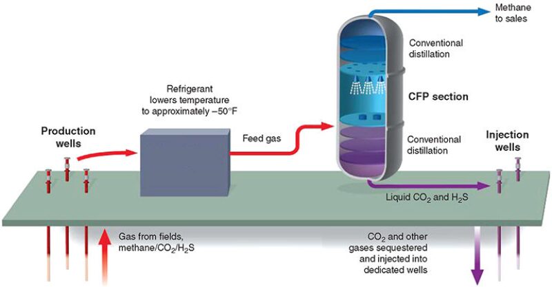
To separate methane at high purity from acid-gas compounds (i.e., CO2 and H2S), a CFP tower normally will use three zones: the specially designed CFP section that addresses the solidification region in the phase equilibrium (pressure/temperature/composition) envelope and two conventional distillation sections for rectifying and stripping, which cover the vapor/liquid areas above and below the CO2-solidification region. In the lower portion of the tower, below the CFP section, methane is recovered or stripped from the bottoms-liquid stream, which contains CO2 and other acid-gas contaminants, by conventional distillation. Above the CFP section, the CO2 content of the methane-product stream is reduced further as needed to meet the required export-sales criteria, again by conventional distillation, this time in a rectifying section.
Liquid (from the upper conventional-distillation section) that is about to enter solidification conditions is sprayed into the CFP section, which is designed to provide an unobstructed space for solid CO2 to form and fall. As the sprayed liquid droplets fall, they encounter warmer temperatures. Methane and any lighter components such as nitrogen, if present, vaporize. The residual concentration of CO2 in the droplets increases, leading to solidification. The solids that form then fall onto a liquid layer at the bottom of the CFP section that is maintained above solidification temperatures. A liquid, now warmer than the threshold solidification temperature, emerges from the bottom of the CFP section and is fed into the stripper section below to recover the methane fraction still dissolved in the liquid as it leaves the CFP section.
Vapor from the bottom conventional-distillation (stripper) section rises through the CFP section and encounters colder temperatures. CO2 condenses or frosts onto the falling spray droplets or solid crystals. The solids formed in the CFP section are pure CO2, thus providing greater separation factors and higher efficiency for this section than conventional vapor/liquid distillation could achieve. Their removal from the vapor stream results in a product exiting the top of the CFP section that is significantly depleted of CO2, and which can be fed to an upper distillation section, if further reduction of residual CO2 is needed.
A test program of the CFP began in early 2012 and was anticipated to last approximately 1 year. This test program aimed at gathering necessary data to design and operate commercial facilities of up to 1 Bscf/D in capacity confidently. At the time this paper was written, the CFP unit had successfully processed gases containing 25 to 71% CO2, reducing the CO2 content in the product stream to much below the targeted 2% pipeline quality, and frequently to less than 1% CO2. Similarly, sufficient methane has been recovered such that residual methane in the bottoms stream is below the targeted 1%.
At 550 psig, the temperatures are colder, the solidification envelope expands, and purities improve. The CFP-section temperatures of −75 to −119°F cover the broader solidification conditions at this pressure. At the same time, vapor emerges from the CFP section with a lower CO2 content, 2.7% CO2, which could meet some pipeline-quality specifications and avoid the need for the rectifying section. At the CFP section, a final-product purity averaging ≈60 ppm, close to liquefied-natural-gas quality (50 ppm CO2), was obtained at 550 psig. Overhead purities of better than 50 ppm were obtained at 525 psig.
Effect of Operating Pressure
The performance of the stripping section, controlled-freeze section, and rectification section was evaluated extensively as a function of pressure. The CO2 content in the vapor leaving the controlled-freeze section changes from approximately 4.5% CO2 at 625 psig to the range of 2 to 2.5% CO2 at 525 psig. These content values are dictated by operating approaches to the thermodynamic solidification-envelope conditions. The CO2 content in the vapor leaving the rectifier is, in essence, the sales product. The CO2 content ranged from approximately 1.5% CO2 at 625 psig, to 0.5 to 2.0% CO2 at 600 psig, to less than 10 ppm CO2 at 525 psig. The rectifier CO2-content values were controlled by the rectifier-packing height and the equivalent number of stages at any given pressure and by the reflux rate used.
Dehydration Requirements
Liquid CO2 has a significant water-carrying capacity that can be used advantageously in reducing the dehydration requirements for the CFP. Typically, feed to a cryogenic process is dehydrated to a moisture dewpoint relative to the coldest temperature in the process, which frequently requires the use of mole-sieve dehydration. Previous CFP-pilot-plant experience had indicated potential viability of alternative, less-stringent dehydration systems.
Laboratory measurements were undertaken to understand the water-holding capacities of methane, CO2, and their mixtures better at pressures, temperatures, and compositions representative of conditions at the demonstration plant. For example, at −51°F, pure liquid CO2 can hold 50 ppm of water, approximately 2.4 lbm/MMscf. This temperature is close to the CFP-feed temperature. Once fed to the CFP tower, the liquid CO2, being the heavier component, moves toward the bottom of the column toward warmer temperatures where the carrying capacity increases to 300 ppm at −23°F, or approximately 14 lbm/MMscf; thus, the hold on the water is more firmly under control.
At the demonstration plant, feed moisture was maintained between 10 and 20 ppm for 1 month with no adverse effects on the feed refrigeration system or in the CFP tower. These are moisture levels that could be achieved with a glycol-based dehydration system. The feed stream contained 66% CO2. Previous shorter-duration tests had shown similar results for feeds containing at least ⅓ of the CO2 dehydrating agent.
Visualization Tests
A laboratory cryogenic spray chamber was built to view (through viewing ports) spray-nozzle behavior and to view solid-CO2 formation in a controlled environment at conditions (i.e., pressure, temperature, and compositions) similar to those experienced in the controlled-freeze section of the demonstration plant. Observing the spray nozzles operating in a cryogenic environment provided understanding of the fluid dynamics within the controlled-freeze section and helped guide nozzle selection. Fig. 2 above is a photo of a nozzle spraying liquid CH4 at −130°F into a vapor containing 15% CO2 at 500 psia and −90°F.
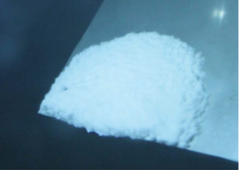
Spray-nozzle behavior at conditions similar to those of the CFP section shows that liquids are sprayed as a dense plume, and the spray-droplet concentration appears to be even across the nozzle-spray area. Similarly, visualization of solid-CO2 formation was undertaken at 500 psia and −95°F. Fig. 3 shows the solid CO2. At these conditions, the solid CO2 appeared to be fluffy in texture, similar to snow. Visualization of solid CO2 enhances the understanding of CO2 characteristics within the CFP section and helps guide operating conditions.
Conclusions and Forward Plans
The CFP technology is a single-step process for separating acid-gas components from methane in sour-natural-gas resources. This is ExxonMobil’s proprietary technology for developing increasingly sour gas reserves around the world. There is no technical limit on the amount of CO2 or H2S in the sour natural gas for treating with CFP technology.
This article, written by Senior Technology Editor Dennis Denney, contains highlights of paper IPTC 16848, “The Controlled-Freeze-Zone Technology for the Development of Sour-Gas Resources,” by J.A. Valencia, SPE, and S.D. Kelman, SPE, ExxonMobil Upstream Research, prepared for the 2013 International Petroleum Technology Conference, Beijing, 26–28 March. The paper has not been peer reviewed. Copyright 2013 International Petroleum Technology Conference. Reproduced by permission.