Closed loop cooling water systems that are critical to the operation of machinery and process equipment depend on heat exchangers. The quality of the water used in the system can adversely affect the integrity and reliability of the heat exchangers, resulting in accelerated corrosion rates, equipment failure, and downtime.
A case study presented at the NACE Corrosion 2014 conference in March determined that the root cause of corrosion failures in a heat exchanger operating in an onshore liquefied natural gas train system stemmed from inadequate system cleaning during commissioning and startup, ineffective microbial control, and subpar monitoring of pH, iron, total suspended solids (TSS), and total bacteria counts (TBC).
Root Cause Analysis of Heat Exchanger Failure
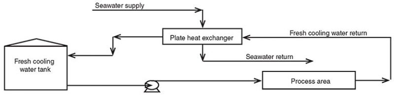
Santuraki and Al-Sayed (2014) described a cooling water system in which fresh cooling water is supplied at a temperature of 38°C and a pressure of 7 bar, while the return water temperature is 48°C at a pressure of 5 bar. The average flow rate of the supplied fresh water is 95,000 ton/hr. A once-through seawater cooling system cools the return water using plate and frame heat exchangers (Fig. 1).
Sodium nitrite, blended with azole (for yellow metal protection), was used for corrosion inhibition, and hydrated sodium borate was used as a buffer solution. A nonoxidizing biocide, isothiazolinone, was used for microbial control.
Historically, only nitrite residual and pH were measured. After a modified corrosion program was introduced, monitoring of the following parameters was done at set frequencies: nitrite residual, electrical conductivity, pH, TSS, iron content, and TBC.
To determine the cause of the heat exchanger failure, the authors studied the inspection reports, historical water parameters, sludge analysis, microbial analysis, and metallurgical analysis of the heat exchanger tubes.
A 69-cm long straight section of a 13-mm outside diameter tube from a failed heat exchanger was used as the sample in the case study. The tube was retrieved after the tube bundle was pulled out for inspection.
The shell and tube design heat exchanger was a nitrogen compressor cooler, with nitrogen on the tube side and cooling water on the shell side. The tubes were Unified Numbering System (UNS) K01200, made of carbon steel ASTM A179, and the shell was UNS K03006, made of carbon steel ASTM 106 Grade B. Before the discovery of the leak, the heat exchanger had been in service for 2 years.
Findings of Inspection and Testing
The tube bundle was found to be covered by a large amount of orange deposit when it was pulled out (Fig. 2). The fresh deposits were wet and sticky and had a distinct hydrocarbon smell. An underlying black deposit was found when the orange layer was removed.

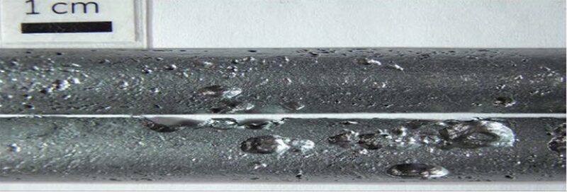
After the deposits were removed for analysis, the tube samples were cleaned by sandblasting. After cleaning, the external surface of the tube displayed deep, irregular depressions filled with metallic and nonmetallic products (Fig. 3). The deepest depression was 2.07 mm, about 90% of the tube wall thickness, corresponding to an average corrosion rate of 44 thousandths of an inch (mils) per year (considering the heat exchanger’s service life of 2 years).
A deposit analysis included loss on ignition (LOI), scanning electron microscopy (SEM) and energy-dispersive X-ray (EXDA) analysis, Fourier transform infrared spectroscopy (FTIR), and microbial examination.
LOI at 550°C was 3% and 4% for external tube (shell side) samples A and B, respectively. The SEM-EDXA results showed that the corrosion product comprised mainly iron and oxygen, with some copper and sulfur in the pits on the tubes. Samples taken from the pits for microbial analysis were negative for total aerobic bacteria, molds, yeast, and sulfate-reducing bacteria (SRB). The authors noted that because the samples were taken 2 days after the tube bundle was removed, bringing into question the viability of microbes, the negative results do not eliminate the possibility of microbial-induced corrosion. A sulfide spot test, used to determine the presence of sulfate-reducing bacteria, was negative. However, the authors said the absence of SRB was inconclusive, because the sulfide might have reacted to form other compounds, or might have been washed away, because the sample was not fresh.
Missed Opportunities for Remediation
Fig. 4 shows periods of low nitrite (corrosion inhibitor) residuals, sometimes below 300 mg/L. Although nitrite levels were restored to the threshold limit (500 mg/L), the cumulative periods of low nitrite residuals were significant. It was found that when nitrite levels were low, the addition of the chemical was delayed from 3 to 4 weeks, because of the lead time required for delivery.
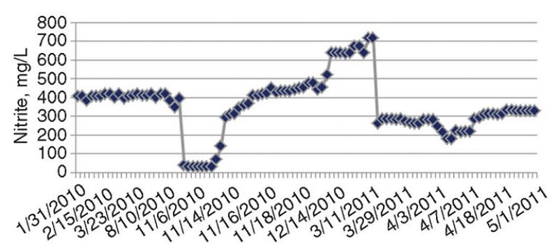
Unexplained depletion of nitrite occurred on some occasions. A confirmed case of leakage from an extracted air cooler was documented as the cause in one nitrite depletion event.
Following the low nitrite events, increasing trends of iron were noted. No coupons were available for determination of corrosion rate. The system also showed high levels of TSS and had frequent heat exchanger blockages.
Santuraki and Al-Sayed said that the increase in iron content during and immediately following the periods of low nitrite levels was an indication of increased corrosion within the system. The increases in TSS seen after the low nitrite conditions were believed to be the results of the presence of the insoluble iron floating around in the system.
If the amounts of TSS in the system are not kept under control, TSS will eventually be deposited in the low areas and dead legs, which can lead to interruption of chemical treatment by preventing the inhibitor from reaching the pipe wall (Herro and Port 1993) and promote microbial underdeposits.
Santuraki and Al-Sayed said that some of the iron was mill scale, which was attributed to inadequate cleaning during the commissioning stage of the system. Pieces of wood chips and remains of welding rods were among the debris recovered when the heat exchanger tube bundle was pulled out. Cleaning activities, including the use of bag filters and physical cleaning of the heat exchangers, were done to reduce the iron and TSS to acceptable limits.
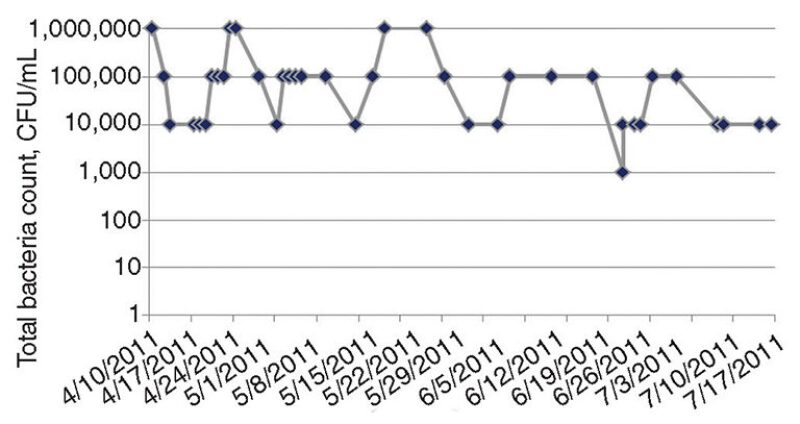
The authors’ microbial analyses showed consistently high TBCs at 1 million colony-forming units (CFU)/mL (Fig. 5). Pseudomonas spp., a slime-forming bacteria, was also found. The authors found that the TBC in the system had not been measured historically. Total coliform counts were mistakenly measured. When the coliform counts were repeatedly negative, biocide dosing was stopped. The dosing was restarted when a new corrosion monitoring program was introduced before the heat exchanger failure.
When the biocide injection was restarted, the system volume was miscalculated, resulting in underdosing of biocide (the total system volume was 30,000 m3, but was miscalculated as 4,000 m3). The system volume was measured when repeated biocide dosing was ineffective in reducing the microbial levels to the threshold limit of 1,000 CFU/mL. At that time, a microbial analysis of the fresh cooling water showed that the microbial population comprised mainly Pseudomonas spp.
Contamination of the System
The analysis of the cooling water indicated the presence of hydrocarbons, chlorides, and high dissolved oxygen levels. It was later discovered that two extracted heat exchangers were leaking and pumping a significant amount of oxygen into the cooling water system. It was also believed that several hydrocarbon contaminations resulted from previous leakages from heat exchangers.
Conclusions and Recommended Practices
The findings in the case study highlighted contributing factors in plant downtime; reduced heat transfer efficiency; expensive equipment cleaning, inspection, and replacement; and increased water and chemical usage.
Corrective actions included isolation of leaking heat exchangers, cleaning and inspection of heat exchangers plugged by slime or debris, system blowdown from low points and dead legs, sidestream filtration, increased nitrite residuals, biocide injection, and increased water chemistry monitoring.
The authors’ recommendations included
- Before commissioning, a closed loop cooling system should be cleaned by flushing with service water, especially at low points and dead legs, combined with sidestream filtration to remove mill scale and suspended solids. A high dose of nitrite can help to form a stable passive film in the system. A high dose of nonoxidizing biocide should be used, especially if the system will be filled with water and left for extended periods of time before the plant is fully commissioned.
- For proper treatment after commissioning, a nitrite program, containing sodium nitrite as a corrosion inhibitor for carbon steel, blended with azole for yellow metal protection and sodium borate as a buffer solution, is cost-effective.
- Maintain residual nitrite levels from 600 mg/L to 800 mg/L at all times. If sulfate and chloride irons are present in the water, the minimum nitrite residual level should be at least five times the total of the chloride and sulfate concentrations combined.
- Regular biocide treatment is required, preferably with the alternating use of two biocides to prevent the microbes from becoming immune to a single biocide over long-term use, to keep microbial levels below 1,000 CFU/mL. Selection of biocides should be based on laboratory screening using samples from the fresh cooling water system. Biocides that are known to promote foaming, such as older generations of quaternary ammonium, should be avoided in closed loop systems.
- Immediately upon opening the heat exchangers during inspection, deposits and swab samples should be collected and transported in a refrigerated container overnight for laboratory bacteria analysis.
- Regular monitoring of water parameters, such as nitrite, pH, TSS, TBC, and iron, are required. When TSS increase beyond a threshold value (depending on the system), sidestream filtration is recommended for cleaning the system.
For Further Reading
Santuraki, M. and Al-Sayed, A.A. 2014. Improving Reliability of Closed Loop Cooling Water Systems, A Lessons Learnt Approach. NACE Paper 4291. In NACE Corrosion 2014 Conference Proceedings, 9–13 March 2014, San Antonio, Texas.Herro, H.M. and Port, R.D. 1993. The Nalco Guide to Cooling-Water Systems Failure Analysis. Boston, Massachusetts: McGraw-Hill.
The Widening Competency Gap in Corrosion Managements shown in the accompanying article, effective asset integrity management can stumble as a result of various factors. Sometimes, the people responsible for the work drop the ball when it comes to putting together the “large” picture necessary for the assessment of a problem. In the case of the failed heat exchanger, missteps occurred as early as precommissioning and continued through a 2-year life cycle.
Ali Morshed, corrosion engineering specialist at Saudi Aramco, highlighted the shortcomings of the traditional education and training of corrosion engineers at the NACE Corrosion 2014 conference in March.
High oil prices in recent years, in tandem with the increasing number of companies that offer integrity management services, have increased the demand for competent and experienced corrosion engineers. Morshed said that university and on-the-job training have been considered the mainstays in preparing engineers for asset integrity management. However, in some cases, the traditional training methods have produced engineers who could not carry out their routine and daily tasks competently and efficiently.
The initial competency of a new graduate engineer depends on the contents, qualities, and the organization of his or her education and training. In many cases, the situation is exacerbated by the retirement of the more experienced and competent colleagues without the transferring or sharing of knowledge and experience with others.
“Universities do a very good job of teaching the students about electrochemistry, corrosion basics and mechanisms, metallurgy, cathodic protection and chemical treatment basics—the engineering related to corrosion. But, they do not do as well in teaching failure risk assessment, the integrity review process, risk-based inspection, production of inspection scopes, or how to determine and use corrosion key performance indicators—the implementation of corrosion management principles,” Morshed said.
Operators and service companies have tried to bridge the resultant knowledge gap by providing mentoring or on-the-job training for their novice corrosion engineers by their more experienced and senior corrosion engineers. In theory, this approach should work.
However, the working environment and the workload are often such that the senior colleagues do not have adequate time to properly and comprehensively train the new engineer, he said. In most cases, the on-the-job training is haphazard and random, which does not promote the transfer of corrosion management knowledge and skills in an organized, structured, and effective manner.
Adding to the difficulty is that the newly recruited engineers have been asked to not only act as the project corrosion engineers (sometimes, with limited, if any, supervision and guidance), but have also been required to perform the project management duties, such as time and resource estimates, time and cost control, and dealing directly with the clients, Morshed said.
He proposed solutions to enable better preparedness of new engineers, including
- Universities should incorporate an introduction to “asset corrosion management” into their engineering courses to emphasize the distinction between corrosion engineering and corrosion management.
- Only senior corrosion engineers who are conversant in corrosion management should be selected to serve as the mentor for the novice engineer.
- The senior corrosion engineer should establish clear and well-defined learning objectives for the on-the-job training, placing emphasis on corrosion management (since the engineering aspects have likely been handled by the university education).
- More senior and experienced corrosion engineers should have opportunities for sharing their knowledge with their colleagues across the company and the industry through “lunch and learn” events, public presentations, or by producing brief technical guidance documents.
Morshed said that the goal is to “highlight to the trainee corrosion engineers that any balanced asset integrity management system comprises both corrosion engineering and corrosion management components.”