There are many reasons a separator may need to be modified: debottlenecking, changing process conditions due to field maturity, increased production, tie-in of new subsea wells, underperformance of the original separator, and so on. Often the separator designer focuses initially on the process side of the modifications. It is in our nature to get started on the computational fluid dynamics (CFD), determine what internals need to be changed, and move forward with solving the puzzle of how all these new pieces will fit into the existing vessel. However, for vessels that are designed to the ASME Boiler and Pressure Vessel Code (BPVC) and are registered with the National Board of Boiler and Pressure Vessel Inspectors, there is more to be done.
What is often left until later is a review of the implications of your retrofit to the vessel’s registration. While the original design, fabrication, and inspection of the pressure vessel was governed by ASME BPVC Section VIII, modifications to a vessel are governed by the repair and alteration section of the National Board Inspection Code (NBIC), NB-23.
In many cases, existing supports and nozzles can be utilized for retrofitting separation internals. In other cases, some welding to the vessel shell or new nozzles are required.
This article highlights some of the code and registration issues the Savvy Separator engineer encounters when retrofitting a vessel with internals and is not meant as an engineering practice. A qualified and experienced engineer should always be involved with the work.
This discussion is limited to changes made to separator vessels that are intended to improve or restore the process performance of the separator. This could mean reconfiguring the internals, changing inlet or demisting devices, adding baffles to change the internal flow patterns, even adding and/or removing nozzles, and similar types of changes. The NBIC uses specific language and the terminology can be somewhat confusing. In simple terms, NB-23 refers to “Repairs” as changes to restore a vessel back to a safe and satisfactory operating state with no deviations from the original mechanical design. NB-23 refers to “Alterations” as changes to anything that was listed on the original data report for the vessel.
| ATCE Special Session By Separations Technology Technical Section |
|---|
The Separations Technology Technical Section is presenting a Special Session, “Separation Insanity—Designing the Way We Always Have To Meet Future Requirements,” at the SPE ATCE in San Antonio on 10 October. Join the Savvy Separators as they discuss chemicals, flow conditioning, full life operating envelopes, and production fluid changes that affect facilities operations. Mark your calendar or register here. |
What are Repairs?
Since separator retrofits are changes to the process side of the separator intended to bring that separator back to a satisfactory state of operation, they are most often considered a repair in the eyes of the NBIC, even though there may not be any damage to the vessel being retrofitted. It is only when the mechanical design of the vessel is impacted that the changes made during a retrofit are considered an alteration.
Examples of repairs are detailed in NB-23, Part 3, Sect. 3.3.3. A few of those examples that would likely be considered as part of a separator retrofit are (as listed in the code):
- The addition of welded attachments to pressure parts, such as:
- Ladder clips
- Brackets having loadings that do not affect the design of the pressure-retaining item to which they are attached
- Tray support rings
- Replacement of pressure-retaining parts identical to those existing on the pressure-retaining item and described on the original Manufacturer’s Data Report. For example:
- Replacement of a shell or head in accordance with the original design
- Rewelding a circumferential or longitudinal seam in a shell or head
- Replacement of nozzles of a size where reinforcement is not a consideration
- Installation of new nozzles or openings of such a size and connection type that reinforcement and strength calculations are not a consideration required by the original code of construction
- The addition of a nozzle where reinforcement is a consideration may be considered to be a repair, provided the nozzle is identical to one in the original design, located in a similar part of the vessel, and not closer than three times its diameter from another nozzle. The addition of such a nozzle shall be restricted by any service requirements
- The installation of a flush patch to a pressure-retaining item
- The replacement of a shell course in a cylindrical pressure vessel
Examples of alterations are detailed in NB-23, Part 3, Sect. 3.4.3. While these are less likely to occur in a separator retrofit, some examples that might apply are:
- An increase in the maximum allowable working pressure (internal or external) or temperature of a pressure-retaining item regardless of whether a physical change was made to the pressure-retaining item
- A decrease in the minimum temperature
- The addition of new nozzles or openings in a boiler or pressure vessel except those classified as repairs
- A change in the dimensions or contour of a pressure-retaining item
The person responsible for insuring that the requirements of NB-23, Part 3 are satisfied is the NBIC inspector. This is an individual who holds a valid and current National Board commission with an “AR” endorsement. The “AR” endorsement allows for the inspection of new construction, in accordance with ASME BPVC, as well as the inspection of repairs and alterations, in accordance with NBIC, Part 3. It is the additional endorsement allowing for inspection of the repairs and alterations of pressure vessels that distinguishes the inspector we need for separator retrofits from those who only inspect new construction. Throughout this article, the term “Inspector” will refer to an NBIC commissioned inspector with an AR endorsement.
Categories of NBIC Changes
When dealing with separator retrofits, the changes that are typically made to a separator fall into four basic categories.
- Minor changes which fall outside the requirements of the NBIC
- Minor changes which fall within the requirements of the NBIC
- Re-rates
- Major changes
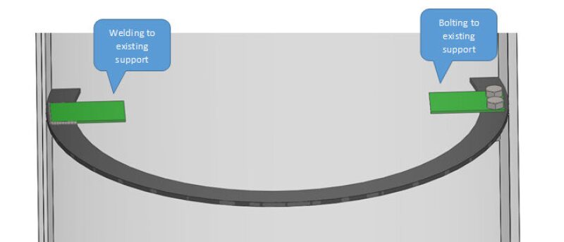
Category 1 are minor changes that fall outside the requirements of the NBIC. That means that such changes do not impact the vessel’s registration and are not subject to requirements of NB-23. These are changes in which there is no welding to any pressure-retaining parts. This would include internals which are welded to, or bolted to existing internal support tabs/rings, internals which are installed using expansion bands, and similar modifications which do not require welding to any pressure-retaining component.
When welding, care should be taken as sometimes other applicable standards and many owner specifications limit how close a weld can be to a pressure-retaining part. This is done to keep the pressure-retaining part outside of the heat-affected zone of the weld. When dealing with a Category 1 change it is still advisable to create a retrofit plan, create an Inspection and Test Plan (ITP), perform pre- and post-inspections, and to document the details of the retrofit. For these types of changes an Inspector does not need to be involved, nor does the vessel require an R stamp or an R-1 form to be completed.
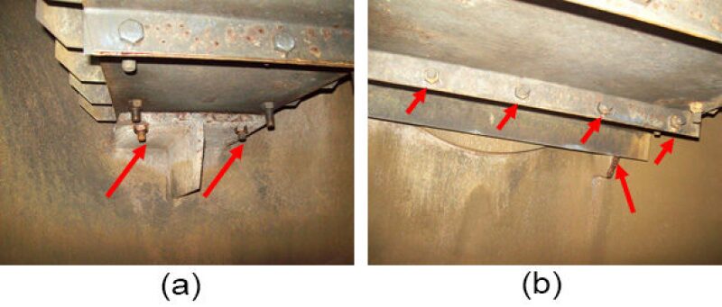
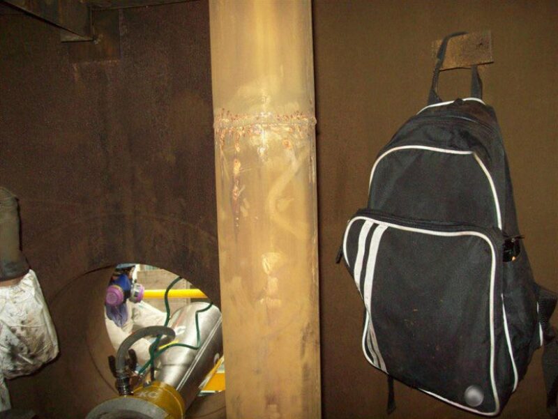
Fig. 1 shows a simple sketch of attachments that fit this category, and Fig. 2 shows photos of separators that made use of existing supports which were trimmed back and used to bolt-in different internals. Fig. 3 shows that existing supports can be useful for a variety of purposes, not just separator internals.
Category 2 are minor changes that fall within the requirements of the NBIC. Minor changes means that these are changes that could be considered as “Routine Repairs” according to NB-23, Part 3, Sect. 3.3.2. These include changes in which there is welding to pressure-retaining parts, but such that they satisfy the applicable requirements of the NB-23.
The portion of Sect 3.3.2 that will most often apply to separator retrofits is subsection e-2: “The addition or repair of nonload bearing attachments to pressure-retaining items where postweld heat treatment is not required”. The major advantage of this category of change is that the requirement of additional stamping and/or testing of the vessel may be waived [NB-23, Part 3, Sect. 5.7.2b] as determined appropriate by the Inspector and the jurisdictional inspector, if required. While still considered repairs by the NBIC, the possible waiving of the stamping and of additional testing greatly simplifies the retrofit process. An R-1 data report is required as is any nondestructive examinations (NDE) required by the design code or the Inspector. It is also a good practice to create a retrofit plan, create an ITP, and to document the details of the retrofit.
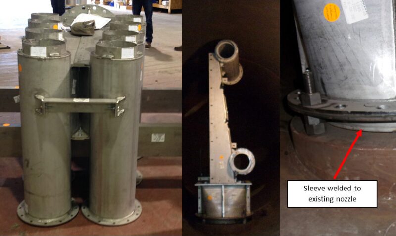
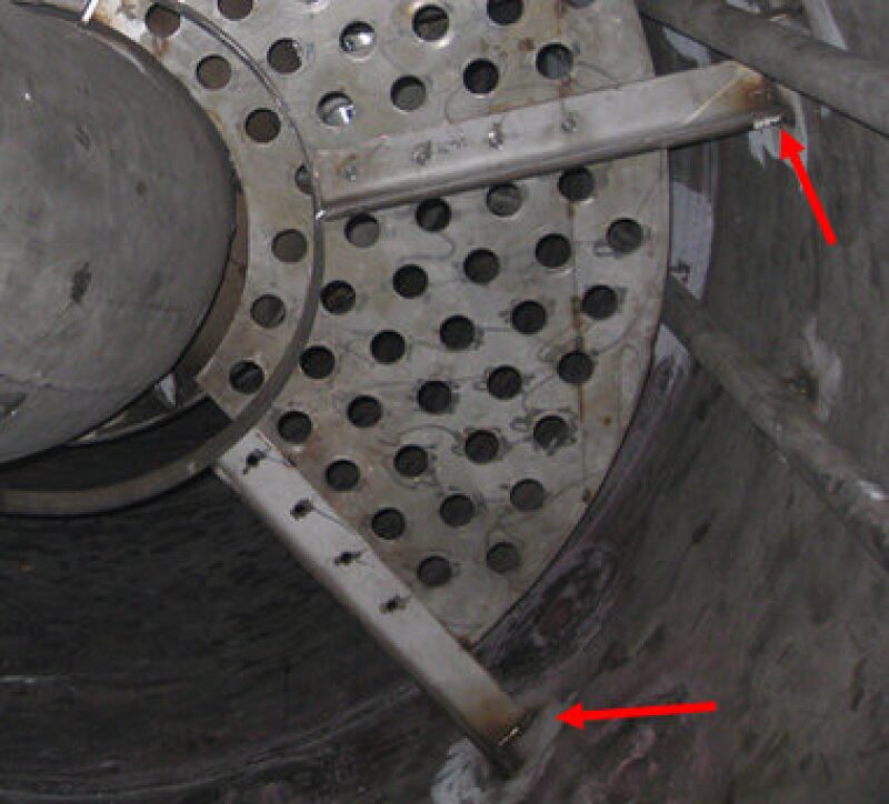
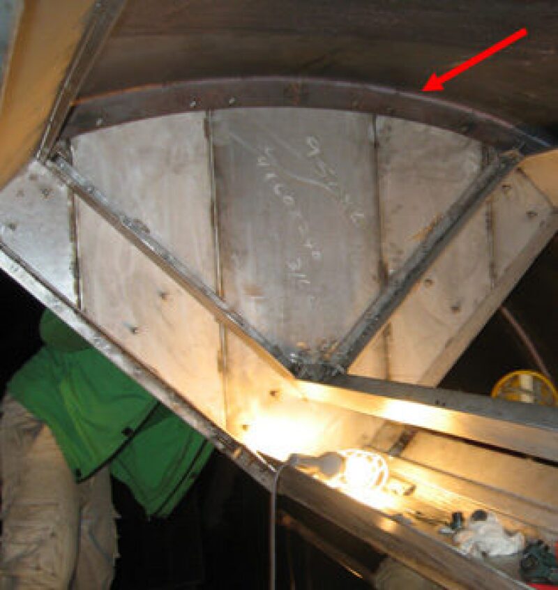
Fig. 4 shows photos of an inlet cyclone device on the shop floor and partially installed in a vessel. The inlet cyclones were bolted to an internal plate flange that was attached to a sleeve and welded to the vessel’s inlet nozzle. In this case, the internal projection was required to meet the nozzle reinforcement requirements, however, the size and method of the weld allowed the Inspector to waive re-hydro testing the vessel. Alternatively, had other weld methods been required, the inspector may not have waived the re-hydro testing. In the case of a nozzle with an internal projection, any excess projection (i.e., more than what is required for nozzle reinforcement) may be considered as a non-pressure-retaining part. However, you should consult with your inspector prior to welding to the excess internal projection of a nozzle. Figs. 5 and 6 are photos of similar small supports which were installed such that re-pressure testing and re-post-weld heat-treating (PWHT) were waived.
Category 3 are re-rates. These are nonphysical changes to the design conditions of the vessel, such as design pressure, design temperature, including minimum design metal temperature, corrosion allowance, or external loadings. A re-rate could be done in conjunction with other changes, but would be considered alterations by the NBIC, regardless of the other changes made to the vessel. Re-rates require a new code calculations, a new nameplate, and an R-2 data report. In addition, the vessel may need to be re-hydro tested, depending on the new design conditions.
Category 4 is major physical changes, or basically anything that will not fit under Category 1 or 2. These are changes such as the addition of large nozzles, shell sections, load-bearing attachments, or anything that requires a significant amount of welding. These may be repairs or alterations, depending on the type of the change. They will not qualify for the waiving of additional stamping or testing. An R-1 or R-2 data report is required, as is a retrofit plan, an ITP, an R-stamped nameplate, and possibly new code calculations and NDE as required by the design code and the Inspector.
Table 1 shows the requirements for each category of modifications listed above. Where appropriate, the sections of NBIC, NB-23 are referenced.
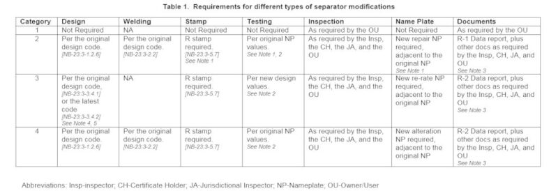
Abbreviations: Insp-inspector; CH-Certificate Holder; JA-Jurisdictional Inspector; NP-Nameplate; OU-Owner/User
Notes:
- Under some circumstances additional testing, inspection, and stamping may be waived by the Inspector, see NB-23, Part 3, Sect. 5.2.6b.
- NDE may be substituted for a re-hydro, if approved by the Inspector.
- Other documents can include procedures for the modifications, weld procedures, mill test reports, NDE reports, hydro reports, inspection reports, etc.
- Under some circumstances the latest edition of the design code may be used in order to take advantage of higher allowable stress values.
In order to use the latest edition of the design code the conditions of NB-23, Part 3, Sect. 3.4.2 must be met. These include:
- Proof of the new design
- Nonlethal service
- Nonfatigue service
- The original vessel cannot have been constructed to a code prior to the 1968 edition of the ASME BPVC.
- The vessel is shown to comply with all relevant requirements of the latest edition of the ASME BPVC.
- The vessel must have a satisfactory operating history and must be inspected to insure there is no damage.
- Approval of the Inspector
- All other parts of NB-23, Part 3 must be met.
- The use of NB-23, Part 3, Sect. 3.4.2 must be documented in the Remarks section of the R-D form.
- Proof of the new design
Onsite or Shop Retrofit?
The location of the retrofit is another factor that must be decided upon. Although extremely rare, there are some situations in which it makes sense to remove the vessel and return it to a shop for the retrofit. The shop offers a much more convenient location in which to make the required changes to the vessel, perform all required NDE, re-hydro the vessel, and/or re-PWHT the vessel, when required. The ability to easily handle and manipulate the vessel essentially eliminates most of the challenges faced with field retrofits. If you are able to return the separator to a shop for the retrofit, consider yourself very fortunate. You may also want to stop and pick up a lotto ticket on your way home from work, because it is your lucky day!
When you are forced to perform the retrofit in the field, things become more challenging. Practices that are easily done in a shop can be near impossible in the field. Field work should be undertaken with the upmost attention to safety, making sure all of the safety requirements are met. In addition, pressure testing and PWHT can be very challenging in the field. ASME PCC-2 Article 5.2 describes changes for which pressure testing is not normally required; it also describes the use of certain NDE methods in lieu of pressure testing. Similarly, NB-23, Part 3, Sect. 4.4.1 addresses pressure testing and alternate NDE methods of pressure vessels.
While there are allowances in NB-23 for an Inspector to waive the pressure testing of a new or modified pressure-retaining component, it is my belief that when practical, most Inspectors will prefer that the impacted component be pressure tested. This can be difficult on-site.
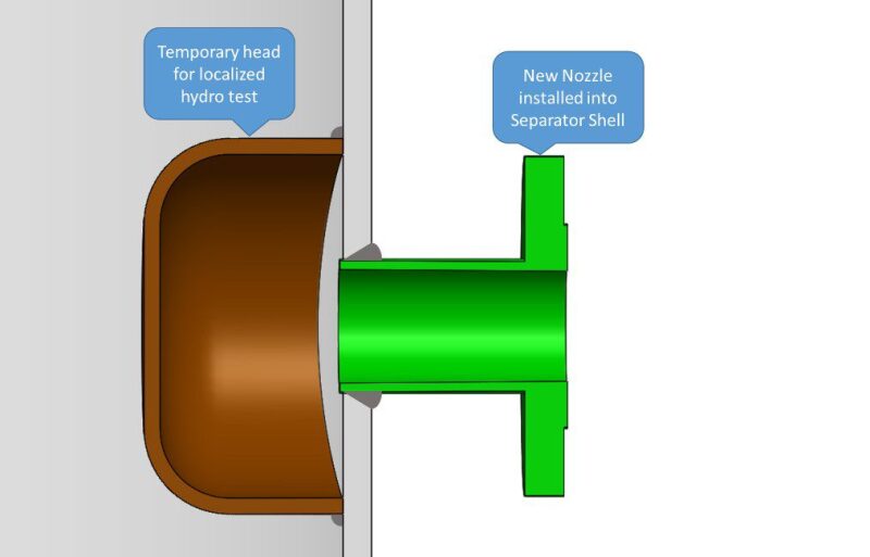
An important fact that should not be overlooked, however, is that a need to hydro-test is for the component and does not mean that the entire vessel needs to be retested. For example, if you add a new nozzle to a vessel, only the nozzle and the nozzle-to-shell weld need to be tested. There may be a simple way to accomplish this. When allowed by the design code, a nozzle, especially couplings, can be installed as “set-on” type nozzles. A set-on, or bossed on, nozzle is one that is literally set onto the outside of the shell and welded into place. In this application, it can be installed and tested prior to the hole being cut into the shell. In some instances additional testing of the shell may be required in order to use set-on type nozzles. For larger nozzles, it may be possible to cover the nozzle with a temporary head that allows the nozzle-to-shell weld to be tested without testing the entire vessel (Fig. 7). Of course, both of these methods must be approved by the Inspector and Jurisdictional Inspector, if required. After the nozzle is tested, the hole is cut, or the temporary head is removed, the area is cleaned up, and any required NDE is performed to insure the shell is unaffected.
Similarly when you are forced to weld to a vessel that has undergone PWHT you face additional challenges. PWHT of vessels can be very difficult in the field. It is generally beneficial to look for alternatives to full PWHT when required on a field modification. NB-23, Part 3, Sect. 2.5.3 and ASME PCC-2 article 2.9 both address alternatives to post-weld heat treatment of modified vessels. These include specific weld methods that allow the vessel to be welded to without negatively impacting the original PWHT cycle. In addition, when special weld methods are not acceptable, localized PWHT may be performed. These are all dependent upon approval by the Inspector and the Jurisdictional Inspector, when required.
Often hydro testing and heat treatment are not practical in the field and in some circumstances may damage the vessel, associated piping, or the supporting and surrounding structure. It is these applications in which it is imperative to involve the Inspector that will be overseeing the retrofit as early in the planning stage as possible.
Another area that may arise during a separator retrofit is the modification of the inlet or outlet piping to the separator. Sometimes the piping needs to be changed to insure that the separator’s performance goals are reached. Changes to piping fall outside the requirements of the NBIC. However, these alterations shall, at a minimum, meet the requirements of the edition of the construction code to which the original component was constructed. [Ref. NB-23, Part 3, Sect. 1.2.6].
While outside the scope of this article, it should be noted that while the NB-23 does not apply other than as noted above, other codes may apply, such as API 570, or other similar codes. Changes to piping and vessel accessories should also be carefully considered by the engineer as these external changes may impact the vessel nozzle loads. Changes to the nozzle loads must be evaluated for any impact they have on the mechanical design of the vessel.
The Inspector is involved in almost all types of separator retrofits. They play an important role in determining what can and cannot be done. This is especially true when it comes to defining what might qualify as a routine repair, when stamping and inspections can be waived, when NDE can be used in lieu of a re-hydro, when alternate weld methods can be used in lieu of re-PWHT, and on and on. It is therefore critical to involve the Inspector in the early stages of most retrofits.
Jurisdictional, State, and Government Requirements
In some instances a Jurisdictional Inspector will also need to be involved with the retrofit. In Texas, there are no additional Jurisdictional rules that apply when retrofitting a separator, but that is not the case everywhere. Some US states and Canadian provinces have additional requirements above those of the applicable design codes and the NBIC. The same is true for some international locations. In those instances, a Jurisdictional Inspector will need to be involved.
For offshore installations things can get a little confusing. If the separator is within state waters (generally extending 3 nautical miles from the low-water mark of the coastline, but in Texas and western Florida the distance is 3 marine leagues or 8.7 nautical miles), then the state has jurisdiction. However, in most US states, California being one of the exceptions, the state defers to the federal regulatory authority for inspection and enforcement. In US territorial waters (extending 12 nautical miles out from the low-water mark) the responsibility for inspection and enforcement is with the US federal authority. Outside the territorial limit, but within the Exclusive Economic Zone (EEZ) (extending from the territorial boundary out to 200 nautical miles out from the low-water mark), responsibility lies with the country that permitted the facility. The federal authority overseeing pressure vessels on offshore platforms seems to be the US Bureau of Safety and Environmental Enforcement with the US Coast Guard possibly having jurisdiction in some circumstances.
The one common thread when dealing with Jurisdictional Authorities is that your Certificate Holder and the Inspector can advise on what should be done and who should be involved with all separator retrofit projects.
There are also additional requirements that are imposed by some Owner/Users. While for many applications, these are covered by company specifications, in the situation where the US government is the Owner, additional requirements like 10 CFR 851, Worker Safety and Health Program, Appendix A to Part 851 Section 4, Pressure Safety will need to be met. Again, the Certificate Holder will likely be familiar with these requirements if they apply.
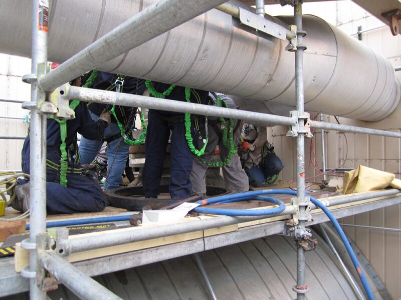
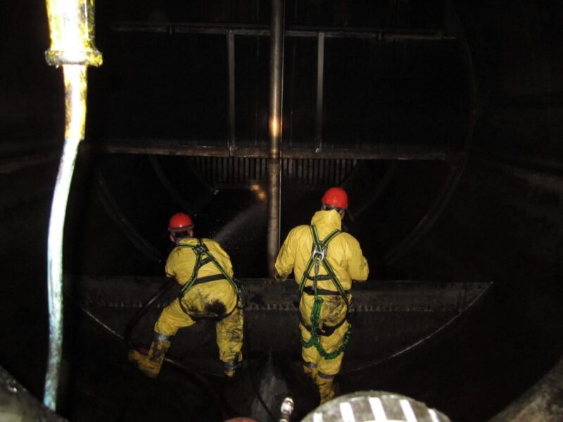
Safety is a major concern with all activities, especially separator retrofits. Separators which have been in service can be filled with residuals of the process. In such cases not only do the site safety practices need to be followed, including all proper personal protective equipment and work practices, but the vessels need to be thoroughly cleaned prior to the commencement of any retrofit activities. An additional consideration is the safe and proper disposal of the waste and scrap removed from the separator being retrofit.
Fig. 8 is an example of a typical separator at the beginning of a retrofit project. Not only does the separator need to be cleaned to provide a safe environment for the workers, but also to provide a clean surface to weld, should welding be involved.
Planning a Retrofit
Planning for a typical separator retrofit will generally follow a sequence similar to the one below.
- Process designer and mechanical designer work closely on the requirements of the retrofit.
- A location for the retrofit work should be determined; either remove and return the vessel to a shop, or determine that the retrofit must be completed in the field.
- The mechanical designer should obtain and review the relevant documents relating to the original separator design, including drawings, code calculations, data reports, material test reports, inspection reports, etc.
- A Certificate Holder is selected to perform the design calculations, separator modifications, etc. Often the Certificate Holder employs the workers that will perform the retrofit.
- The Certificate Holder develops a retrofit plan and involves the Inspector for review of that plan.
- All applicable safety requirements are reviewed and incorporated into the retrofit plan.
- The mechanical designer shall consult all appropriate personnel, such as the primary Inspector (i.e., the inspector holding an AR endorsement from the NBIC who is responsible for the separator retrofit), Jurisdictional Inspectors, insurance inspectors, licensed engineers, or other persons when required in order to develop designs that are in compliance with the requirements of the jurisdiction and all applicable codes and standards.
- Iterations between the Certificate Holder and the designers can take place as needed to arrive at the most practical solution that ensures the integrity of the pressure vessel while allowing for the needed modifications to be made to the separator.
- The final design and retrofit plan should be submitted to and approved by all those having approval authority. This can include, but is not limited to, an NBIC Inspector, an insurance inspector (these are often the same inspector), a Jurisdictional Inspector (if required), a Professional Engineer, an appropriate employee of the Owner/User, and an appropriate employee of the Certificate Holder.
- The Certificate Holder shall develop an ITP for review and approval by all required parties.
- The retrofit plan is executed and goes off without a hitch (so, I’m an optimist!).
Additionally, when estimating the timing of the retrofit project some of the minor activities can be overlooked. Don’t forget to allow for cleaning the separator prior to work; erecting scaffolding within the vessel; dry/cure time for internal coatings; removal of scaffolding; and cleaning the separator after the completion of work. These and other similar activities can often be overlooked when a project schedule is created, resulting in unexpected and costly delays.
In short, the easiest way to have a retrofit plan be executed with few or no issues is to plan well, involve the certificate holder and Inspector early in the process, and work together to develop a plan that achieves the process goals with minimal impact to the vessel’s registration.
Definitions:
All definitions are taken directly from NB-23, Part 3, Sect. 9.
Alteration. A change in the item described on the original Manufacturer’s Data Report which affects the pressure containing capability of the pressure-retaining item. (See NB-23 Part 3, Sect. 3.4.3, Examples of Alteration) Nonphysical changes such as an increase in the maximum allowable working pressure (internal or external), increase in design temperature, or a reduction in minimum temperature of a pressure-retaining item shall be considered an alteration.
Authorized Inspection Agency. Inservice: An Authorized Inspection Agency is either:
a) a jurisdictional authority as defined in the National Board Constitution; or
b) an entity that is accredited by the National Board meeting NB-369, Accreditation of Authorized Inspection Agencies Performing Inservice Inspection Activities; NB-371, Accreditation of Owner-User Inspection Organizations (OUIO); or NB-390, Qualifications and duties for Federal Inspection Agencies (FIAs) Performing Inservice Inspection Activities.
Inspector. An individual who holds a valid and current National Board Commission.
Certificate Holder. An organization in possession of a valid “R” Certificate of Authorization issued by the National Board.
Field. A temporary location, under the control of the Certificate Holder that is used for repairs and/or alterations to pressure-retaining items at an address different from that shown on the Certificate Holder’s Certificate of Authorization.
Inspection. A process of review to ensure engineering design, materials, assembly, examination, and testing requirements have been met and are compliant with the code.
Jurisdiction. A governmental entity with the power, right, or authority to interpret and enforce law, rules, or ordinances pertaining to boilers, pressure vessels, or other pressure-retaining items. It includes National Board member jurisdictions defined as “Jurisdictional Authorities.”
Jurisdictional Authority. A member of the National Board, as defined in the National Board Constitution.
Jurisdictional Inspector. An inspector certified by the Jurisdictional Authority to verify conformity to all jurisdictional requirements.
Nameplate. Identification plate mounted onto the vessel. This can include the original design nameplate, a repair, a re-rate, or an alteration “R” nameplate.
NBIC. The National Board Inspection Code published by The National Board of Boiler and Pressure Vessel Inspectors.
Owner/User. As referenced in lower case letters means any person, firm, or corporation legally responsible for the safe operation of any pressure-retaining item.
Repair. The work necessary to restore pressure-retaining items to a safe and satisfactory operating condition.
Shop. A permanent location, the address that is shown on the Certificate of Authorization, from which a Certificate Holder controls the repair and/or alteration of pressure-retaining items.
References:
National Board Inspection Code, NB-23, 2015 Part 3, “Repairs and Alterations.”
ASME Boiler and Pressure Vessel Code, Section VIII, 2015.
ASME PCC-2-2015, “Repair of Pressure Equipment and Piping.”
Acknowledgement
The author wishes to thank Russ Scinta, lead mechanical engineer with Schultz Process Services, and Keith Gilmore, Authorized Inspector with TÜV Rheinland, for their invaluable assistance with this article.
Thanks to current and past Separations Technology Technical Section officers and directors for their contributions. A list of current members can be found here.

Jay Stell is the vice president of engineering with Schultz Process Services, Inc. (SPS). He holds BS and MS degrees in mechanical engineering from The University of Texas at Arlington and a PhD in mechanical engineering from Purdue University. Stell has worked in the separation industry since the early 1990s with more than 25 years’ experience with Burgess-Manning, Peerless Mfg. Co., and now with SPS. He has spent the majority of his career in product development, separator design, laboratory and field testing, and troubleshooting. He can be reached at jay@spshouston.com.