
Troubleshooting and solving separation problems takes a combination of analytical tools, experience, and a knack for investigation. Asking the right questions for information and then synthesizing that information can consume a significant amount of time and resources. However, once the problem is solved, some key messages stay with you for solving future issues. This article will discuss several examples of troubleshooting separation problems and the main lesson learned from each one. The applications cover issues related to solids, droplet shearing, maldistribution, and instrumentation.
1. Look for the Simple Solution
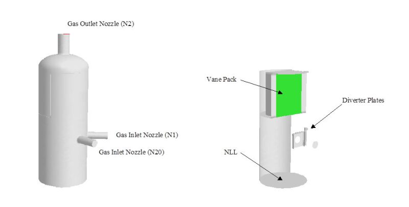
Fig. 1 depicts a typical gas scrubber with a side inlet nozzle (N1) and a top gas outlet nozzle (N2). The only internals in this vessel are a vertical vane pack and an impact plate that has a hole cut out with the same diameter as the inlet nozzle. The problem with this vessel was twofold: no incoming liquid was being captured plus the liquid in the vessel was being lost. Sometime in the past, the impact plate was believed to be contributing to the problem, hence the hole cut out. A second inlet nozzle (N20) was not being used, but also had a similar impact plate with a hole.
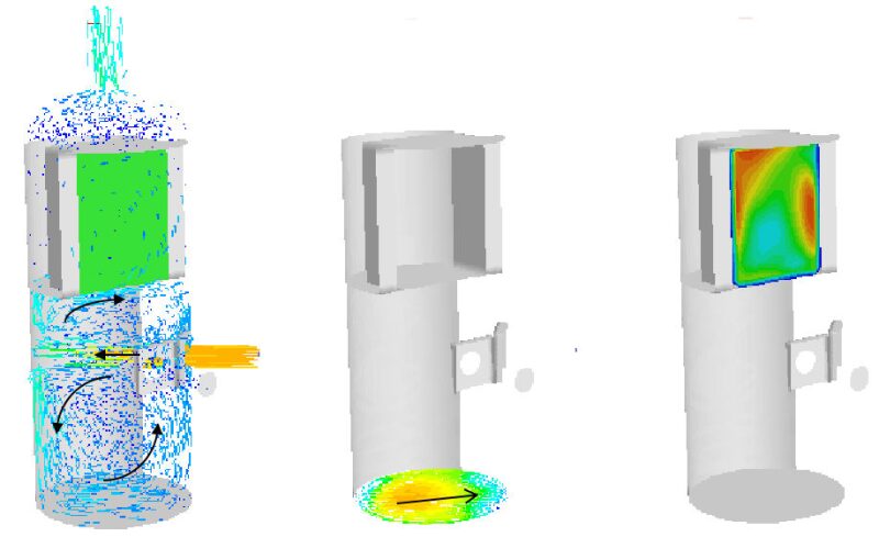
High gas velocities and maldistribution, of course, rise to the top of the suspect list. Computational fluid dynamics (CFD) was used to model the gas flow inside the vessel and results are shown in Fig. 2. Fig. 2a shows gas velocity direction and magnitude (red/orange depicting high velocity, and blue low velocity). Some arrows have been drawn to show the general flow pattern. The high-velocity inlet jet impacts the back wall and creates two recirculation zones, one above and one below the gas jet. The recirculation zone in the bottom part of the vessel results in high-enough gas velocities across the liquid surface (Fig. 2b) to re-entrain the liquid. Furthermore, due to the recirculation zones, the gas flow through the vane pack is maldistributed (Fig. 2c) so that liquid droplets are not removed.
A potential solution would be to retrofit the scrubber with a vane-type inlet and, because of the high gas rates, a set of demisting cyclones. This type of retrofit would be somewhat complex because of the requirement to be able to use either inlet nozzle and the required cyclones would have completely filled the vessel diameter. Because high gas velocities were at the root of the problem, it was recommended to first try lowering the gas velocity by using both inlet nozzles simultaneously and lowering the liquid level as low as possible. This solution worked and the scrubber worked satisfactorily.
The lesson learned here is that once you know the root cause of the problem, look for a simple solution first. Assess what you have available and significant time- and cost-savings may be realized. Question whether the originally specified carry-over limit is required, because it may lead to an unnecessarily complex and costly solution.
2. Get the Whole Picture
Fig. 3a shows a dehydration (oil/water separation) plant with two trains, A and B. The trains are similar with water being removed in freewater knockout vessel(s) (FWKO) followed by an oil dehydration settling tank. Water from both trains is treated in a common system (de-oiling tank, flotation cells). The problem in this situation was that Train A was suffering from upsets (wet sales oil).
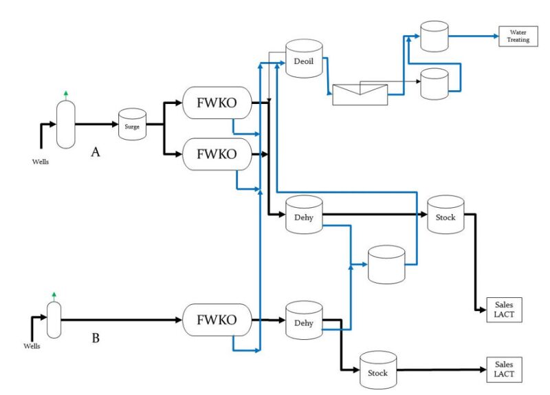
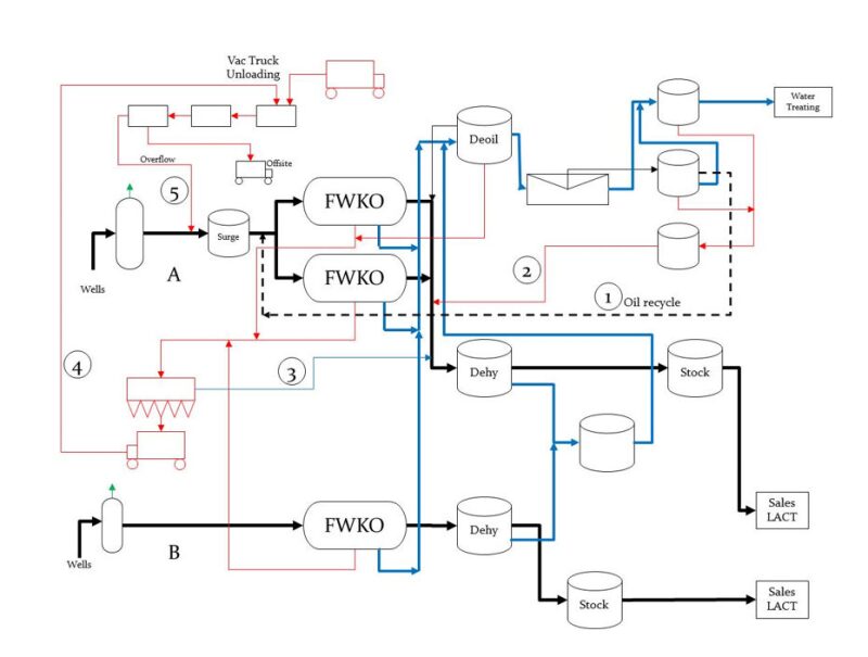
Fig. 3b shows the rest of the flow connections and it becomes clear why Train A suffered from upsets. Oil (1) removed from the water is recycled to Train A’s FWKOs. Solids/bottoms (2) from the water plant tanks are recycled to the Train A dehydration tank. Solids (3) from the FWKOs and the de-oiling tank are processed in a simple separation tank with the separated liquids returning to Train A’s dehydration tank. Finally, the solids (4) that are removed are dumped into a vacuum truck handling facility where the overflow liquid (5) comes back into Train A. In addition, the recycle solids/fluids were not steady, but were dumped quickly (high-/low-level switching) resulting in high percentages of solids and slop oil flowing into the Train A separators.
The lesson learned in this example is the importance of getting the whole picture. The above application encompassed many process streams that were spread out over miles and had many operators. Put all the flow streams on one sheet of paper and the root cause (and solution) may become obvious. Sometimes, you may be aware of the local issues, but when you see them all together, the severity of the problem becomes evident.
3. A Solution to One Problem May Lead to Another Problem
Fig. 4 shows a large tri-grid (bi-electric) desalter. The oil/water mixture flows through a header and is distributed between the electrical grids via 10 risers. A schematic of the riser is also shown in Fig. 4 (restrictions not shown). Dry oil is then removed by the outlet header pipe. With the intent of increasing capacity, the vessel had been converted from a low-velocity desalter where the oil flows from below two electrical grids.
After the conversion, the outlet oil was wetter even at lower flow rates compared to prior to the conversion. The external desalter mixing valve was not changed so small droplet size was suspected due to all the restrictions inside the desalter, which were believed to have been installed to obtain uniform fluid distribution. Hence, the fluid distribution, pressure drop, and the resulting water droplet sizes were estimated along the flow path. The estimated riser base pressure drop was on the order of 1 psi and about 3 psi across the slots. It was clear then that a very good fluid distribution existed with 5% of the inlet flow exiting each of the 20 radial slots. On the other hand, water droplet sizes on the order of 10–15 microns exiting the slots were estimated to be a result of the shearing through the restrictions/pressure drops.
Subsequent modifications reduced the estimated pressure drops and increased the droplet size by a factor of 4–5. Fluid distribution per slot suffered, but was within 10% of being uniform. The resulting water in oil was reduced by a factor of two, and the desalter was operating satisfactorily.
The lesson learned is that a solution to one problem may lead to another problem. In this example, very good fluid distribution was created by the restrictions/pressure drops, but small droplets resulted which the electrical grids could not quite overcome. Look for knock-on effects of modifications.
4. Build a Mockup for Complicated Retrofits
This example was previously discussed in detail. A scrubber was retrofitted with new internals (to reduce liquid carry-over) as depicted in Fig. 5. Fig. 6 shows the actual internals and the complexity of the retrofit is pretty evident.
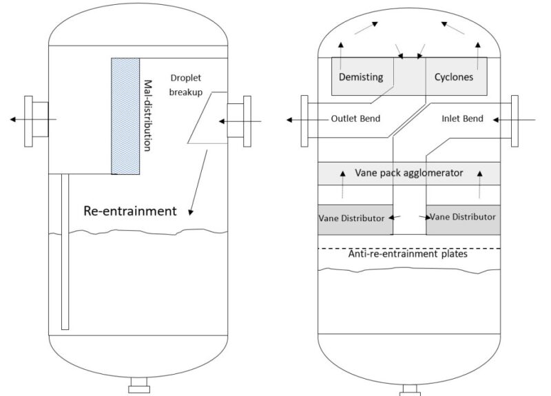
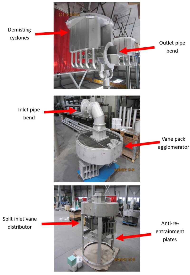
The vessel has an inside diameter of approximately 56-in. and its seam to seam height is 9 ft. The manway is 18-in. in diameter. The installation of the internals is complicated by the small space. And as with any retrofit, the internals are bolted together in a particular order.
The lesson learned here is building a mockup vessel to practice complicated retrofits. Installation difficulties can be identified. For example, problems in tightening bolts can be found that may require special tools or a redesign of the internal. Or perhaps an awkward lift position can be avoided.
In some cases, the time required for executing a retrofit in the field will be the critical path for a shutdown. Training the installation crew in a mockup vessel can aid to reduce actual downtime of the plant.
5. Remember Sherlock Holmes
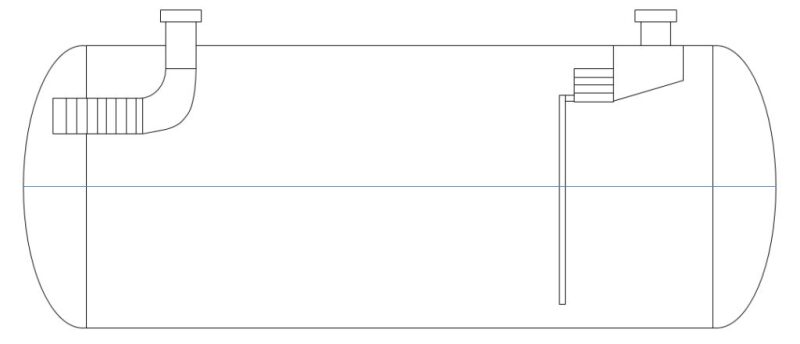
This troubleshooting example is a favorite of the author. An approximately 10-ft ID×30-ft long two-phase separator vessel was outfitted with a vane-type inlet and demisting cyclones. This was not a difficult separation case with the gas space K-factor being on the order of 0.09 m/s. However, when the vessel came on line, massive carry-over was reported and even no liquid capture at all: basically, what went into the vessel went right out the gas outlet.
The following troubleshooting steps were conducted as listed below along with the results or findings:
Check instruments (by field personnel)
- Checked calibration
- Observed liquid in vessel only at low rates
Checked vessel gauges
- Instruments OK
- Instruments OK
- Checked calibration
Check if operating conditions different than design
Checked PVT for liquid volumes
- Within design
- Within design
Check sizing of internals
- Reasonable inlet momentum
- Low gas K-factor
Enough cyclones
- Internals properly sized
- Internals properly sized
- Reasonable inlet momentum
Checked flow distribution
- Modeled inlet pipe flow with CFD plus estimated droplet shatter
Modeled vessel gas phase flow with CFD
- Vessel should be separating liquids
- Vessel should be separating liquids
- Modeled inlet pipe flow with CFD plus estimated droplet shatter
The above effort was significant, but no root cause was evident. But in this situation, we are reminded of a quote by Sir Arthur Conan Doyle as spoken by his Sherlock Holmes character in “The Sign of the Four:”
“How often have I said to you that when you have eliminated the impossible, whatever remains, however improbable, must be the truth?”
Although, in this case, we could not eliminate the impossible to a 100% degree of surety; separation experts felt certain that the pressure/volume/temperature, the internals, and the flow paths were not the issue. And based on the author’s experience, the instrumentation was still a suspect. A field visit was not possible. But we were reassured that the instruments were operating properly. As it turns out, the root cause was finally found reportedly to be that the differential pressure level transmitter was hooked up backwards. So instead of having no level, the vessel was practically filled with liquid so no liquid dropout was possible as well as flooding the demisting cyclones.
So the lesson learned is remembering Sherlock Holmes. Eliminate or rank potential causes.
Summary
Troubleshooting and solving separation problems can sometimes be frustrating. But the experience gained will help in future issues as long as you remember how you found the cause and solved the problem. This article highlights, through the use of examples, five lessons that the author has learned and continues to use. These are:
- Look for a simple solution
- Get the big picture
- One solution can cause another problem
- Build a mockup, and
- Remember Sherlock Holmes
References
Chin, R.W., Van Asperen, V., Riesenberg, J., and McVinnie, G. 2015. The Savvy Separator Series, Part 3—Scrubber Debottlenecking. SPE Oil and Gas Facilities.

Robert Chin is a cofounder and past chair of the SPE Separations Technology Section, past chair of the SPE Gulf Coast Section’s Projects, Facilities, and Construction (PFC) study group, a member of the SPE Annual Technical Conference and Exhibition’s PFC paper selection committees, and the author of Chapter 3, “Oil and Gas Separators,” in the SPE Petroleum Engineering Handbook, Volume III, Facilities and Construction Engineering. Chin is a consultant and cofounder of Padden Engineering. He retired from Shell in 2014. He joined the company in 1981 and conducted advanced research on multiphase flow, leak detection, and separations. In 1999, he left the company to form a separator design and supply company. He returned to Shell in 2006 and led teams in facilities for enhanced oil recovery and subsea processing research and development. Chin holds a degree in applied mathematics and a PhD in fluid mechanics from Harvard University. He may be reached at r.w.chin@sbcglobal.net.