
The officers and directors* of the SPE Separations Technology Technical Section represent more than 250 years of experience in the industry. Throughout their careers, they have developed savvy from what has been passed on to them from their own mentors, lessons learned the hard way, or learned as good practice. In any case, their ghosts of separators past visit us in this article so that we do not repeat the same mistakes in the future.
The lessons learned list that follows is neither exhaustive nor prioritized and may seem obvious. However, even for the experienced, it can be a checklist for proper design. Your feedback, sharing of lessons learned, and savvy are most appreciated.
*Current members: Jimmie Riesenberg, Victor van Asperen, Brad Nelson, Flavia Viana, Spencer Oulman, Mika Tienhaara, Hank Rawlins, Manoj Bulsara, Graeme White, Jay Stell, Norman Yeh, Richard Arntzen, and Cris Heijckers. Past members who contributed to this article are Ed Grave, Chris Buckingham, and Robert Chin. The authors thank Ken Arnold, Jose Bravo, Doug McCammon, and Graeme Smith for their contributions.
The Design Process
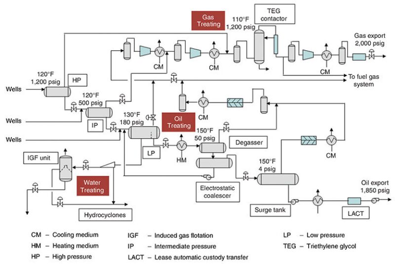
The separation process must be understood and designed as a system. The oil/water/gas/solids process facility is made up of interconnected systems (Fig. 1), so it should be designed holistically with the entire system in mind. In the past and still sometimes in the present, the production separators, gas scrubbers, water treating systems, and gas treating systems are designed by different engineers without connecting the dots between the systems. The gas scrubbers may be supplied as a package from the compressor dealer who may be assuming the presence of little liquid in the inlet gas stream. The designer of the gas treating system may not be expecting that crude oil will get into the glycol tower, and the water treating designer wants oil droplets that have not been shredded in an upstream control valve.
The other considerations are the recycle streams and the most appropriate return locations to minimize contamination and hence, the effect on the efficiency of separation, and ensuring whether experienced operators have been involved in the design process from the beginning, when design changes are more easily implemented (many design engineers have limited operations experience).
The operators are more accustomed than the compartmentalized design team to thinking about the system as a whole. Good, working communication lines and information sharing are key within the project team, not only among the staff of the oil company’s operations such as project, mechanical, and process engineers, but also with the engineering contractor, vessel fabricator/packager, and internals vendor.
Effect of Operating Conditions on Design
The biggest impact on a good or bad design is good or bad design input data. Getting the design basis right and including startup, shutdown, blowdown, early/mid/late life operations, and alternate operating cases all impact the design and can be used to determine the required real operating envelope.
It is important to include water cut and compositional changes expected over the life of the operating facility. Potential contaminants, foam, emulsion, and solids all impact separations. Even the production chemicals injected, especially methanol and glycol, can affect separation performance.
Slug volumes alone are insufficient for design; the composition of the slug needs to be considered. Is the slug all hydrocarbon, all water, or the same oil/water ratio as the normal production? The frequency of slugging and how fast it can be drained from the vessel, combined with the ability of downstream equipment (e.g., pumps) to tolerate liquid rate changes, impact the volume in the vessel allotted for the incoming slug.
Do not use a steady-state three-phase separator as a slug catcher. Use a freewater knockout on the liquid outlet of the slug catcher to separate oil and water. A mist extractor on the gas outlet of a slug catcher may easily be flooded with liquid when processing a liquid slug. It is better to not have a mist extractor in the slug catcher, and, if possible, to install a downstream separator with an appropriately sized inlet diverter, gravity settling section, and mist extractor for average gas flow. Never flow gas from a slug catcher directly to a compressor. Mesh demisting designs are particularly susceptible to fouling (plugging). In the event of a fouled mist extractor, a full shutdown may be required to clean it out.
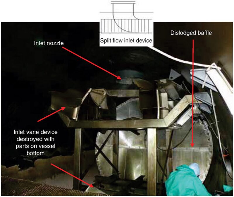
Also, consider the effect of slugging on the mechanical design of the inlet devices, as there may be much higher inlet momentums (Fig. 2).
Operating conditions not only include rates, pressure, and temperature, but also reaction times between liquid levels. Be aware that the separator may not work at all conditions, especially with internals. Do not be alarmed if when 15 years down the road, you have to retrofit the vessel to handle the late life low pressures.
Consider the production profile and, in particular, the produced water in early life. In most situations, produced water will begin coming after a number of years with initial rates being low. This results in the produced water system not being commissioned until years after first oil and the system being vastly oversized for the initial produced water rates, often requiring expensive temporary treatment. Consider if having trains for the produced water system makes more sense and provides better flexibility.
Fluid Properties
Do the fluid properties make sense? Does a 1 lbm/ft3 gas density make sense at 1,500 psi? Obtain the process data in real units, such as kg/m3 for density or actual ft3/min for flow rate. Do not accept specific gravities.
Process simulators provide several values of specific gravity. Were you given a liquid specific gravity and assumed it was the operating value, only to find out later that you were given the dead oil specific gravity? Actual flow rates are necessary. Designs cannot be based on standard condition flow rates and densities. Note that conversion from standard to actual conditions for gas requires the compressibility and molecular weight.
If the data sheet specifies two phases (gas and liquid), make sure that there are only two phases involved in the process (and that the real liquids have not been combined into a pseudophase). Oil and water are essentially immiscible liquids. Therefore, there will be water droplets and hydrocarbon droplets in the gas and not simply liquid droplets. The design has to account for all the droplets and their properties for separation.
Table 1 shows a case in which the water and condensate properties were combined into a single liquid property for the scrubber design. The scrubber had excessive carry-over, but when comparing the operating data to the design data, it was noted that it should have instead had an appreciable margin as the operating load factor was 0.21 m/s while the allowed using the supplied properties in the liquid column of the table was 0.30 m/s.
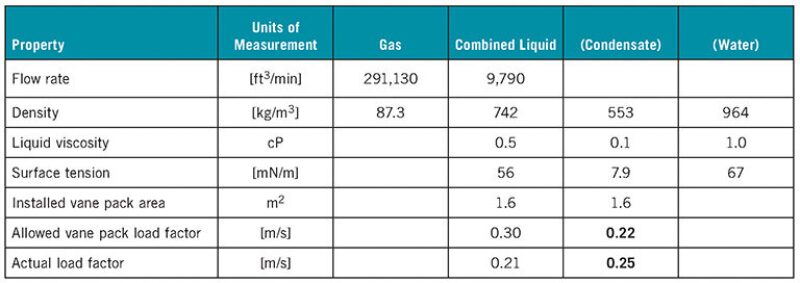
When taking a closer look at the liquid phase properties in the table, something was found to be not right. The density indicates a light/medium crude oil, so the viscosity could be plausible, but the surface tension is much too high—it should have been around 20 mN/m or less instead of the listed 56 mN/m.
Checking the piping and instrumentation diagrams revealed that this vessel sees a two-phase liquid flow. It turned out that the process engineer making the design data sheet combined the condensate and water properties (listed in the last two columns of the table), and this specification had slipped through the reviews.
Substituting the condensate liquid phase properties results in an operating load factor of 0.25 m/s compared with an allowed 0.22 m/s, a 15% overload, explaining the carry-over. After installing a larger vane pack, the scrubber worked satisfactorily. However, the downstream compressor had already been damaged by the carry-over and required costly repairs.
Other necessary considerations: Does the simulator output make sense, especially for surface tensions or oil viscosities? Do you know the specific meaning of the supplied value for the liquid surface or interfacial tension (e.g., air/liquid or gas/liquid)? Get viscosities and surface/interfacial tensions (if practical) from laboratory measurements and not from a simulator. Make sure that all parameters which could impact equipment size and performance are clearly understood. Bear in mind the uncertainties related to the fact that only a thimbleful of the reservoir was available for characterizing the feed. Determine when you can and cannot rely on simulation-generated fluid properties, and consider the changes in fluid properties over the life of the field.
Pay close attention to fluid properties in relation to water chemistry. Conduct a thorough scale indexing to determine when/where scale will occur and implement a scale inhibitor program. Take particular notice of how a subsea tieback’s compatibility will impact the current inhibitor program. Do your homework on seawater compatibility to prepare for when breakthrough occurs.
Separation Efficiency
Understand the fluid outlet requirements within a systemwide perspective. Are the requirements for separation efficiency or liquid carry-over properly defined? Consider the gas in the liquid as well as the liquid in the gas exiting the separator. Efficiency can be a very deceiving parameter since it is dependent on total inlet variables. What does the downstream equipment actually require, and what is the impact on the downstream process of more water in the oil or more oil in the water?
The most poorly used specification for liquid carry-over is the 0.1 gal/MMscf for production separators. This is a compressor scrubber specification which is not appropriate for high liquid load vessels. Have you calculated what this requirement means in terms of actual separation efficiency? You may be surprised that in many cases the additional separation efficiency achieved with this specification will be in the fourth decimal place (99.999X%). Do you really want to specify a 0.1 gal/MMscf liquid carry-over limit in a production separator if you have a downstream scrubber? Avoid over- or underspecifying the required efficiency, and do not copy generic specifications or the specifications from a previous project (unless you are sure they apply).
Instrumentation
The control system may provide a liquid-level percentage which is quite different from the gauge reading you will see when you leave the air-conditioned control room and check the gauge with your own eyes. Visit the facility and talk to operators. Performance models are approximations of reality and, when used or extrapolated outside their ranges, may give incorrect results. Always question computer-generated data, which do not replace common sense.
Understand the level instruments. If you have a mixture near the interface/surface, different instrument principles may give very different level readings. Are the instruments calibrated at the right process conditions? You may have a triethylene glycol contactor level instrument calibrated for the differential pressure of glycol/ambient air pressure, but it may have been decided to operate the column at 80 bar.
When large changes in production rates occur, having a single control valve for the entire range may result in poor controllability and excessive shearing. Make accommodations for either parallel control or the changing out of control valves over the life of the facility.
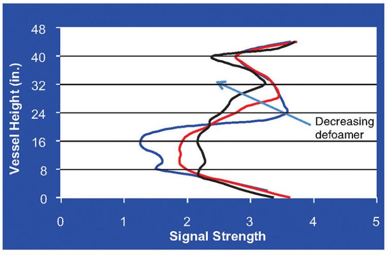
Watch for a liquid level inside the vessel different from that shown by density-based level instrumentation, which could be caused by foaming. Fig. 3 shows a gamma scan density profile as a function of a defoaming chemical. The external level instrument displays an unchanged level while the foamy level increases in the vessel as the chemical decreases. The high foam level will result in liquid carry-over, although you might be led to believe that the liquid level is sufficiently low enough for good separation.
Physics
Think about and understand the physics behind the equations used in the design of separators. Do not use them blindly. Performance in air/water simulators is a poor indicator of performance in high-pressure hydrocarbon systems.
Excellent sizing parameters may be determined by observing what works in analog fields and using those parameters as the scaling parameters for the equipment being sized. For example, knowing the retention times and droplet settling diameters for both oil in water and water in oil for an analog piece of equipment in an analog field allows you to use the same parameters for sizing equipment for a new, but similar, application. However, you must be certain that you are using a good analog. For example, the viscosity may not be the same, but understanding how viscosity affects separation may allow the scaling of the analog to the new case.
Recycle
Do not recycle rag layers or wet oil back to the front of the production train. Have a separate train for the treatment of “bad” oil. Rag layers will build up over time at the oil/water interface, and you may be mixing chemicals from the water treating process into the oil, which may result in adverse effects. Too much chemical can itself cause a rag layer.
Solids
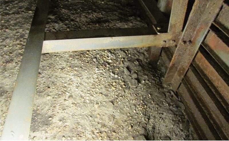
Accommodate for the removal of solids and design for handling solids (proper jetting design). Quite often, the separator performance has deteriorated and the principal cause is solids accumulation. Make note of the point that we refer to “solids,” and not “sand.” In numerous instances, the separator’s sand jets or cyclones are not used because the thought is that “we are not making sand,” but the vessel may be 30% full with scale precipitants (Fig. 4).
Automate the solids removal system where possible to make it easier for the operators to use, thereby encouraging their use of it. Many times the system will be manual, onerous, and over time, less frequently used, which leads to more expensive intervention. Automating the system may cost more initially, but it will allow regular usage while significantly reducing cost, increasing uptime, and avoiding production restrictions in the long term.
Sample and Injection Points
Make sure you have sampling points (on inlet and outlet streams and on the separator) for qualitative performance assessment. Although sample points are a “leak” source, knowing whether liquid exists where it should not or if you have a rag layer is invaluable for troubleshooting.
Understand the best locations for injection points for the specific chemistries to be used. For example, demulsifiers work better with more retention time, so design the injection of chemicals as far upstream of the inlet separator as possible.
Safety
The No. 1 priority is to protect people and the environment. Double check the design. If you followed the first lesson of system design above, your hazard and operability study will proceed more smoothly.
Provide the appropriate operations training to the operators. This is above and beyond the “principle of operation” training that component vendors may provide. Strive to develop a thorough “system” training program that includes sections describing causes and effects for troubleshooting purposes.
Adhere to a strict routine maintenance program. The simplest things often can manifest into major upsets. Clean, repair, and replace items as needed such as chemical injection pumps, level/interface controllers, solids accumulation, and plugged sample ports to avoid the progression resulting from the neglect of a simple routine fix into a major upset and ultimate shutdown.
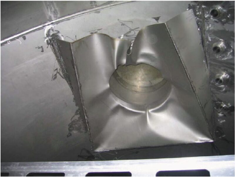
Keep in mind the simple items. Fig. 5 shows a failure in a deflector plate due to excessive forces created by the high exit velocities at the Visund platform in 2006 (Lauridsen, Eltervåg, Sande et al.). (Whether a deflector plate should have been in the vessel to begin with is another issue.) This failure resulted in a gas leak, platform shutdown, and evacuation. Fortunately, there were no injuries as emergency procedures and other barriers worked as designed.
Conclusions
A “savvy separator” is not unlike a good project and/or operations team. It is only as strong as its weakest link. Numerous factors impact separator performance, and this article points to the importance of considering them all during the separation sizing and operation. If applied correctly, you will not be woken up in the middle of the night by clanking chains, or worse yet, a phone call from the operations manager.
For Further Reading
Petroleum Safety Authority (PSA) Norway, Incident Report (in Norwegian): Investigation of a Serious Gas Leak From the Pressure Relief System at Visund on 19 January 2006 by Ø. Lauridsen, A. Eltervåg, E. Sande, and P.E. Endresen, Petroleumstilsynet (Petroleum Safety Authority Norway). http://www.ptil.no/getfile.php/z%20Konvertert/Helse,%20milj%C3%B8%20og%20sikkerhet/Hms-Aktuelt/Dokumenter/visundgranskingsrapportutennavn1.pdf (accessed 2 November 2015).
PSA Completes Investigation of Visund Incident (20 June 2006),http://www.psa.no/news/psa-completes-investigation-of-visund-incident-article2733-878.html (accessed 2 November 2015).

Robert Chin is a cofounder and past chair of the SPE Separations Technology Section, past chair of the SPE Gulf Coast Section’s Projects, Facilities, and Construction (PFC) study group, a member of the SPE Annual Technical Conference and Exhibition’s PFC paper selection committees, and the author of Chapter 3, “Oil and Gas Separators,” in the SPE Petroleum Engineering Handbook, Volume III, Facilities and Construction Engineering. Chin is a consultant and cofounder of Padden Engineering. He retired from Shell last year. He joined the company in 1981 and conducted advanced research on multiphase flow, leak detection, and separations. In 1999, he left the company to form a separator design and supply company. He returned to Shell in 2006 and led teams in facilities for enhanced oil recovery and subsea processing research and development. Chin holds a degree in applied mathematics and a PhD in fluid mechanics from Harvard University. He may be reached at r.w.chin@sbcglobal.net.