Developments in the processing of sour gas were the topics of several papers presented at the 2014 Abu Dhabi International Petroleum Exhibition and Conference (ADIPEC) last month. Sour gas reserves, historically left undeveloped because of the technical challenges and cost involved in their extraction and processing, are being revisited as potential sources of supply in areas with high demand for natural gas. Only in recent years has technology advanced to an extent that makes processing of sour gas with high carbon dioxide (CO2) and hydrogen sulfide (H2S) feasible.
The Middle East region is particularly interested in tapping its challenging gas reserves, of which 60% are sour. The United Arab Emirates’ annual rate of natural gas consumption is expected to increase from the current 2.8 Tcf to 5.2 Tcf by 2015, and 6.3 Tcf by 2020. The area’s swift demographic and economic growth in the past decades has resulted in a rapidly expanding electricity grid that relies on power generated by natural gas-fired facilities. The demand for electricity is also outpacing the natural gas supplies in Saudi Arabia and Kuwait.
The USD 10 billion Shah field gas project in UAE, the largest sour gas project in the world, is nearing completion with approximately 98% of the development done. The field was discovered in the 1960s, but was not considered technically feasible to develop.
Abu Dhabi Gas Development Company (Al Hosn Gas), a joint venture partnership between ADNOC and Occidental Petroleum, aims to extract 1 billion scf/D of well fluid containing 23% H2S and 10% CO2 from the Shah field. The plant will provide approximately 500 million scf/D of clean natural gas for the Abu Dhabi market, 4,400 tons per day of natural gas liquids, 33,000 B/D of condensate, and 9,200 tons per day of elemental sulfur for agricultural and industrial uses.
Other sour gas fields are also being evaluated or developed. The Bab sour gas field in the UAE is expected to start production in 2020. The Hail field in the UAE is being evaluated, and ongoing projects include the South Gas field in Iraq, the Mabrouk field in Oman, and the Manifa field in Saudi Arabia.
Technical Challenges
H2S in the gas stream is toxic and flammable. Safety training for personnel is a critical requirement to prevent injuries and deaths. It can damage drilling equipment, and during the production and transportation of the natural gas, H2S and CO2 can cause corrosion in the pipelines. Also, the removal of CO2 from the gas stream is necessary because high concentrations decrease the energy yielded in combustion. For transportation of liquefied natural gas, the concentrations of CO2 must be less than 50 parts per million volume (ppmv) to prevent blockage of flowlines and other operational problems that result when CO2 freezes during the chilling of the gas to approximately –160°.
Sulfur Removal and Recovery
Generally, H2S removal from natural gas with subsequent sulfur recovery is performed in amine and Claus plants. These processes are considered economical for quantities of sulfur greater than 50 ton/day. In a paper presented at ADIPEC, Hauwert (2014) reviewed processes for small-scale sulfur recovery from sour associated gas, including liquid reduction/oxidation (redox), Thiopaq O&G, CrystaSulf, and direct catalytic oxidation. He described the processes as being applicable for removal of sulfur quantities ranging from 1 ton per day to 20 tons per day, for direct treatment of high-pressure natural gas and low-pressure associated petroleum gas, and for sulfur recovery from low-pressure acid gas.
Liquid Redox. The liquid redox processes are traditionally selected for recovery when the sulfur load is too small for the Claus process.
Redox methods use an alkaline solution with high-valent metal ions, such as vanadium (Stretford process) and iron (LoCat and SulFerox processes). The metal ions convert the dissolved H2S into elemental sulfur and are then regenerated by oxidation with air. The sulfur content is generally 80% weight (dry) and can be upgraded to 99.5% by washing and smelting, Hauwert said. Because the process solution is aqueous with hydrophobic (i.e., repel water) solid sulfur particles, plugging and foaming may occur and cause operational problems.
Thiopaq O&G. The process (Fig. 1) uses naturally occurring bacteria (Thiobacillus) to oxidize H2S to elemental sulfur. The bacteria consume sodium bisulfide ions formed after the feed gas is scrubbed with a mildly alkaline sodium hydroxide solution and excrete elemental sulfur, which is separated from the circulating solution.
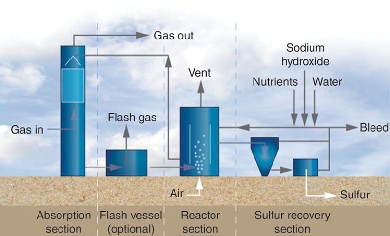
The H2S is removed to ppmv levels, and the produced sulfur is hydrophilic (i.e., it has an affinity for water) and is not sticky, which reduces operational issues, such as plugging of process piping and equipment.
Developed in the 1990s by Paques for desulfurization of biogas, the Thiopaq O&G process was modified by collaboration with Shell Global Solutions for application at high pressure in oil and gas environments. The first commercial Thiopaq O&G unit for natural gas was built in 2002. The process is licensed by Paqell, a joint venture company of Shell Global Solutions and Paques.
CrystaSulf. The Gas Research Institute developed the process (Fig. 2) in the 1990s for H2S removal from high‑pressure gas. Operating similarly to a liquid-phase Claus process, it uses a nonaqueous hydrocarbon solvent which contains sulfur dioxide. When the solution comes into contact with the gas containing the H2S, elemental sulfur and water are formed, Hauwert said. The sulfur dissolves in the solvent and is precipitated in a scraped-surface crystallizer to decrease plugging and foaming. H2S is reduced to ppmv levels, and for associated gas applications, no foaming or negative effects from hydrocarbon condensation are expected. However, for large, low-pressure gas flows with limited H2S content, the solvent can be costly.
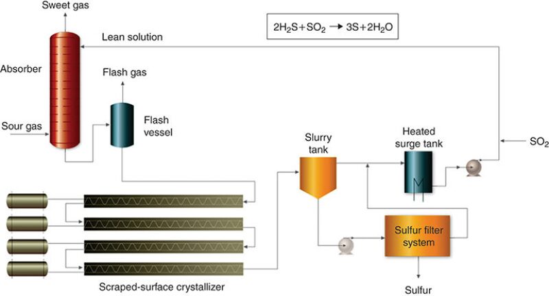
Hauwert noted a commercial application of the process in Germany, where Gassco operates the Norsea gas terminal along the North Sea coast and a network of gas pipelines that transport the associated gas from North Sea oil platforms to onshore processing plants. In 2005, CrystaSulf was installed at the facility so that the sales gas could meet a total sulfur specification of 3.3 ppmv and reduce the amount of scavenger injected for control of H2S on an offshore platform in the network.
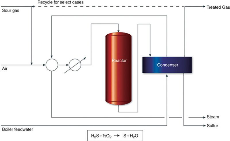
Direct Catalytic Oxidation. TDA Research developed the process (Fig. 3), which is licensed by GTC Technology. Applicable to lean acid gas streams, the process converts H2S directly into sulfur by using a catalyst. The company said it is effective for sulfur recovery ranging from 0.1 ton per day to 200 tons per day and that the sulfur conversion efficiency is approximately 90% in a single pass.
Testing Materials in High and Ultrahigh Pressures
The presence of acid gases (CO2, H2S, and sulfur) in production fluids can cause general and localized corrosion, depending upon the physical and chemical properties of the fluids. Materials selection for facilities that process the fluids is generally determined by experience and guidance by standards and regulations.
The predication of corrosion rates is better understood for CO2 than for high-pressure H2S, according to Gabetta et al. (2014). The authors cite the difficulties in performing laboratory tests in high-pressure conditions as a contributing factor for this difference.
As a testing standard, NACE water-based solutions A and B are used to simulate production fluids in equilibrium with H2S gas at 1 bar to assess the sulfide stress cracking susceptibility of steels. The authors said that the low pH and chloride in the solutions and the 1 bar testing conditions may not represent the actual environment in which the materials are used.
For example, gas mixtures are treated at high pressure and high temperature at reinjection plants in production fields that contain high H2S and/or CO2 content. Although the gas mixture in injection wells is dry, the authors recommend the consideration of the presence of a small quantity of water or vapor that could be present as the result of short periods of upset. In cases where methane, CO2, and H2S are mixed at high pressure with a small amount of water, a liquid phase is present and rich in H2S and/or CO2—conditions in which corrosion is likely.
To simulate high and ultrahigh gas pressures, Gabetta et al. used a high-pressure autoclave (Fig. 4) to test materials with H2S and gas mixtures at pressures up to 1000 bar. The equipment comprised an internal vessel with a volume of approximately 1.6 liters. The inner volume was adjustable by pressurization of the water contained in the external chamber.
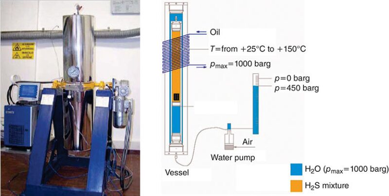
The test materials were held in contact with the pressurized mixture, with or without water. A H2S/CO2/methane mixture was used to simulate reinjection conditions. The autoclave operated at temperatures up to 150°C.
Four-point bend beams with dimensions 100×20×2.5 mm were tested. The specimens were:
- Carbon steel API 5L X52, sour service grade
- Carbon steel F22, sour service grade (UNS K21590)
- Low-alloy steel API 5CT grade T95 type 1, sour service grade
- Austenitic steel type AISI 316L (UNS 31603)
- Nickel-based alloys (UNS N008825 and N006625), including Iconel
A test condition simulated reinjection conditions (ultrahigh pressure). A small percentage of a water solution simulating production water was tested at 90°C and total pressure 720 bar. A test to simulate high pressure used NACE solutions A or B pressurized with H2S gas at 50 bar or 100 bar.
The surfaces of the specimens were ground to 600 grit sandpaper. Their intial conditions were examined by stereomicroscope. Stress levels were applied based on the actual yield strength of the specimens, except for the Iconel material, for which the stress was based on the percentage of strain.
Test Results
Tested only in ultrahigh pressure conditions, the carbon steel API 5L X52 showed some shallow pits on the surface when water was present. The pits appeared wider when larger quantities of water were used.
The carbon steel F22 showed diffuse pitting, similar to cracking, after testing in high pressure and ultrahigh pressure conditions.
The low-alloy steel API 5CT grade T95 type 1 sample failed during some high pressure tests, but showed wide and shallow localized corrosion (no cracks) in the ultrahigh pressure tests. The authors noted that the results suggested the NACE solutions were too conservative to simulate high-pressure H2S because field conditions are mostly dry or have low water content.
Measurements of weight loss showed that the corrosion increased with higher H2S pressure in the NACE solutions. In the ultrahigh pressure tests, the weight loss was lower, but increased with a higher content of water.
The austenitic steel type AISI 316L showed surface cracking in ultrahigh pressure tests with water, and high pressure tests with NACE solutions at temperatures greater than 80°C and in the presence of chlorides. No general corrosion was observed.
The nickel-based alloy (with and without weld) did not show failure or corrosion. Only a slight change in color of the sample's surface was observed. Test conditions were at 720 bar and 830 bar at 90°C.
As sour gas reserves are increasingly targeted for exploitation, the costs and efficiencies of processing facilities are a major factor. The authors encourage further development of testing conditions and methods to close the gap between field conditions and laboratory tests to improve materials selections in facilities.
For Further Reading
SPE 171874 Challenges and Achievements in Safe Sampling and Accurate Analysis of Sour Gas by U. Veerakumar,J. Josham Al Ali, and A. Abbas, Abu Dhabi Gas Liquefaction.
SPE 171950 Tests in Ultra High Pressure of H2S by G. Gabetta, Eni, A. Pontarollo and S. Sgorlon, VeneziaTecnologie.
SPE 171968 Enhancing the Value of Sulphur: Using Sour-to-Acid as Field Development Concept by M. Gierman,M. Lebel, and P. Micone et al., Shell Cansolv.
SPE 172058 Sweetening and Sulfur Recovery of Sour Associated Gas and Lean Acid Gas in the Middle East by P. Hauwert, Frames.