Engineers who design separators often refer to industry literature that provides rules of thumb. While useful, the theoretical guidelines are typically written for downstream separators and are difficult to apply to the changing dynamics of upstream field conditions and the challenging nature of today’s crudes.
Mike Power, senior process engineer at BP, said the industry literature describes two approaches for designing a separator: one using residence time and the other using Stokes’ law cut point. He spoke at a recent webinar, “Gravity Separator Design: Theory vs. Practice,” sponsored by SPE’s Separations Technology Technical Section.
Residence time describes the length of time that it takes for water to separate from oil with a given density. It is based on research conducted by the American Petroleum Institute in the 1940s on downstream separators and provides guidelines for separator sizes on the basis of how long it takes for an oil-and-water mixture to settle into different components. It factors in the density of the oil, but not its viscosity.
Stokes’ law is used to estimate how long it takes for a droplet of a liquid (usually water) to pass through a lighter liquid (usually oil) inside a separator. Cut point refers to the diameter of the water droplet to be separated from a given water/oil mixture or a water/oil/gas mixture.
To achieve equilibrium of the mixture, the separation vessel must be of a certain size. In a hypothetical example, Power used Stokes’ cut point to calculate how long it would take for a drop of water 500 µm in diameter to pass through 1 m of oil with a given density and viscosity. It would take approximately 2 minutes for the water to pass through oil with a viscosity of 4 cp. If the viscosity of the oil increased to 50 cp, the settling time would increase to 60 minutes. The viscosity of the oil can have a “profound effect” on the length of time that it takes to settle, he said. Power recommended Stokes’ law over residence time because it takes into consideration the oil’s viscosity.
The majority of the technical literature that describes how to design separators considers the removal of water droplets 150 µm in diameter to be “good separation,” and the removal of droplets 500 µm in diameter to be “bulk separation,” he said. Theoretical specifications for a separator generally apply to inflows of 5% to 15% water in oil, or for processing 1,000 ppm or less oil in water.
For upstream separators, there is no typical distribution for water in oil and the droplet size changes as it enters the vessel, which makes the rules of thumb difficult to apply.
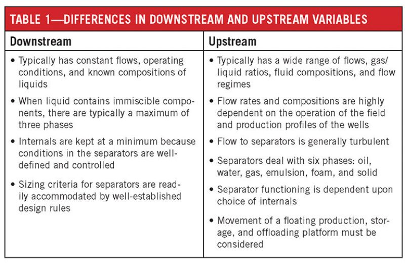
The 150-µm droplet size is applicable to downstream separators, which have relatively constant flows, operating conditions, and known compositions of liquids and gases. “Typically, for downstream operations, we know very well what the flow conditions are,” Power said. Therefore, the sizing criteria for downstream separators are accommodated by the design rules.
However, “upstream separators face a wide variety of operating conditions,” he said. They have varying degrees of gas/liquid ratios, fluid compositions, and flow regimes, including slugs, mist, and annular flows. The production profiles of the wells can lead to changes in the flow rates and compositions over time. For example, BP has separators that were originally designed to process crude with a viscosity of approximately
5 cp, but today are receiving oil with viscosity in excess of 100 cp.
Another challenge in the design of upstream separators is the turbulence of the inflow, which can consist of a total of six phases: oil, water, gas, emulsion, foam, and solid. Downstream separators generally have a maximum of three phases, Power said.
When engineers try to apply the theoretical design rules to an upstream separator, the result can be a separator in excess of 50 m long, because of the variation in conditions.
To cope with the additional challenges of designing an upstream separator, BP has compiled a database of cut points that are applicable to sets of field conditions. Although valuable, Power said the database is valid for oils with viscosities of less than 10 cp. However, a growing portion of heavier oils with a viscosity exceeding that level are now being produced globally. He was uncertain how applicable the data are to fields that produce crudes with higher viscosities.
While Stokes’ cut point is more useful than residence time, it has limitations. For example, its ideal application is for laminar flows. For an upstream separator to function in the field as Stokes’ law predicts, the turbulence of the inlet stream must be reduced or eliminated.