
The world’s first offshore gas-hydrate production was carried out successfully in deepwater Japan at Nankai trough in 2013. In this project, one production well and two sandface monitoring wells were drilled and installed with a combination of distributed-temperature-sensing (DTS) and array-type resistance-temperature-detector (RTD) sensors. The objective of the sandface-monitoring system was to capture the hydrate-dissociation front dynamically changing during the production test and to monitor long-term reservoir stability with the selected temperature sensors.
Introduction
Interest is growing worldwide in methane hydrate as a unique and challenging natural-gas resource. In order to produce and use these resources, it is necessary to establish the production technology and understand how methane-hydrate dissociation behaves. Japan has studied methane-hydrate exploration during the past decades and planned to conduct the world’s first offshore methane-hydrate production test in 2013. In such a production test, the dissociation progress and the stability of the methane-hydrate reservoir can be captured by long-term continuous temperature monitoring, which is conducted in real time and autonomously before, during, and after the production test.
One of the more challenging requirements is that the deepwater sandface-monitoring system must be self-operated by subsea battery without cable connection from the surface for a long-term monitoring period of 18 months. Thus, the reliability and redundancy of the monitoring system were key design challenges above data measurement quality and offshore deployment tasks.
Outline of the Sandface-Monitoring Wells
One production well and two monitoring wells were drilled. The methane-hydrate reservoir in the Nankai-trough area has methane-hydrate-bearing sand-rich intervals in turbidite fan deposits. For the production test, approximately 50 m of methane-hydrate zone was selected that is located in shallow unconsolidated reservoir approximately 300 m below the seafloor in a water depth of 1000 m.
Deepwater sandface-monitoring systems were deployed in the two monitoring wells in the first quarter of 2012, approximately a year before the methane-hydrate production test started in the first quarter of 2013. The production test continued for a week, and then the recovery of the sandface-monitoring systems was performed in the third quarter of 2013. Therefore, the in-situ temperature monitoring started 1 year before the production of methane hydrate and continued for approximately half a year after the production test in order to monitor the long-term stability of the methane-hydrate-reservoir behavior. After the monitoring system was recovered from the seafloor, temperature data were retrieved from data storage for analysis.
Sandface-Monitoring-System Solution
In order to have seamless long-term temperature monitoring with restricted access of both communication and power from the sea surface, the sandface-monitoring system was specifically designed for autonomous self-operation by subsea battery with a programmable measurement schedule. In addition to autonomous operation, real-time communication to the sandface-monitoring system on the seafloor could be established either with wet-mate cable connection for cable communication or with acoustic communication through seawater.
The sandface-monitoring system consisted of the following four main system components:
- Downhole (inside monitoring wells)
- Subsea (on the seafloor table)
- Subsea/surface (subsea cable)
- Surface (on the drillship)
For the downhole sensors, the combination of DTS and array-type RTD sensors was selected to maximize the values gained from the acquired temperature data in terms of the depth and time coverage, measurement resolution, and accuracy. DTS covered the entire wellbore interval at 0.5-m resolution, while RTD sensors were placed strategically across the hydrate reservoir at 2-m spacing. This had the benefit of acquiring data from high-precision-point sensors such as RTD sensors because this hydrate reservoir has finely laminated formation layers. The total number of RTD-sensor modules was 35, which covered the entire hydrate reservoir. The temperature resolution and accuracy specification are 0.002°C and ±0.1°C, respectively. These were the highest specifications ever offered for hydrate-reservoir monitoring.
Fig. 1 shows a diagram of the downhole-deployment method of DTS cables and array-type RTD sensors. The DTS acquisition unit was installed inside the well-designed pressure vessel known as the “orange ball,” where the temperature-measurement data were recorded per the predefined measurement schedule and stored into memory inside a subsea acquisition board. In addition, the subsea battery was located inside the orange ball to supply the power to the DTS acquisition unit for autonomous self-operation. The controller board incorporates circuitry to control and monitor the supply of power to the DTS acquisition unit and to data-channel communication with an external surface computer, an acoustic communication modem, and the DTS acquisition unit.
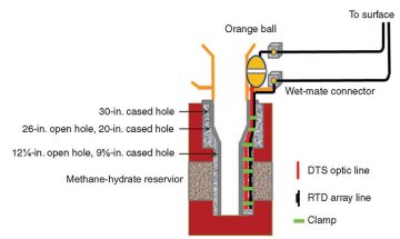
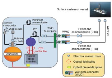
Fig. 2 is a diagram of the system connectivity, in which wet-mate connectors were used to enable the physical connections of the cables to the sandface-monitoring system on the seafloor by remotely operated vehicle (ROV), an innovative design that has expanded the options of managing the risks in reliability and redundancy in this project. For example, RTD cable from downhole is fed directly to the electrical wet-mate connector without interrupting the pressure vessel, and the data are sent to the vessel at surface directly through the subsea cable. This feature has two unique advantages. It separates the operating lines of RTD sensors from those for DTS in the pressure vessel so that a failure of one system will not affect the operation of the other. Another point of superiority with this system architecture is that it enables the real-time acquisition of RTD data at surface.
Offshore-Deployment Challenges
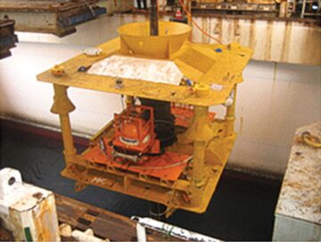
The deployment of the monitoring system in a deepwater offshore operation was one of the more critical paths to the success of this project. There is a possibility that the monitoring system and devices could be affected detrimentally during riser- and casing-running activities at the wellbore. Thus, a requirement was developed to have a robust design for the monitoring system, and the simplified deployment procedure will facilitate the flexibility for field deployment to align with offshore operation. The deployment operation was conducted with the departure of the monitoring system at the moonpool located below the drill floor, as shown in Fig. 3. RTD sensors and DTS cables were run behind the casing into the open hole of the monitoring well. The deployment of RTD sensors and DTS cables in open hole in deepwater was an extraordinary and challenging operation; therefore, customized cable protectors were designed to protect the sensor cables. This cable protector was functionally designed to be able to be installed at either casing cup or midjoint, while preventing vertical slippage and maintaining the balance between the cement flow and the casing centralization. After the monitoring system was landed on the seafloor, the monitoring well was completed with cementing activities in which both RTD sensors and DTS cables were cemented behind the casing.
Although the monitoring system was exposed to high shock and vibration several times at the sea surface during the deployment because of rough weather, a functional system test conducted at the surface through cable and acoustic communication confirmed that no functional failure occurred. The installations for the monitoring wells were completed successfully in March 2012. The DTS temperature-data acquisition continued its autonomous self-operation from deployment until the recovery of the monitoring systems in August 2013. During the production test in March 2013, the subsea cable was attached along the riser on the top of the blowout preventer above the wellhead of the production well and then connected to the monitoring system by ROV assistance. Consequently, the temperature data can be monitored in real time at the surface during gas-hydrate production to the surface.
Summary
Understanding how the methane-hydrate dissociation progresses and understanding the stability of the reservoir constitute the fundamental knowledge to be established before attempting commercial production of methane from a hydrate reservoir. The ability to monitor reservoir temperature continually during the dissociation process not only reveals the track of the dissociation propagation but also provides the most practical temperature-data input to develop the numerical methane-hydrate-reservoir simulators to predict the hydrate-dissociation rate.
The robust design of the deepwater sandface-monitoring system was developed to enable the long-term temperature monitoring of the methane-hydrate reservoir in the Nankai trough. A pressure vessel was designed and built with an integrated subsea battery and devices to allow self-operated temperature acquisition. The deployment was successful and continuously obtained high-quality temperature data over a 1.5-year period.
This article, written by Special Publications Editor Adam Wilson, contains highlights of paper OTC 25328, “A Deepwater Sandface-Monitoring System for Offshore Gas-Hydrate Production,” by S. Chee, SPE, T. Leokprasirtkul, T. Kanno, O. Osawa, Y. Sudo, M. Takekoshi, and H. Yu, SPE, Schlumberger, and K. Yamamoto, Japan Oil, Gas, and Metals National Corporation, prepared for the 2014 Offshore Technology Conference, Houston, 5–8 May. The paper has not been peer reviewed. Copyright 2014 Offshore Technology Conference. Reproduced by permission.