
Pumping Oil: 155 Years of Artificial Lift
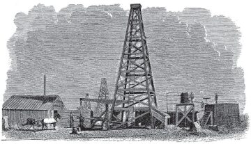
On 27 august 1859, near Titusville, Pennsylvania, USA, “Colonel” Edwin Laurentine Drake found “rock oil” in a well he deliberately drilled to produce it.
It was not just the oil that ushered in the modern petroleum era, but also the rig and tools Drake and his driller, saltwater-well expert and blacksmith “Uncle Billy” Smith, used to drill and pump the oil from the well.
“[T]he production end of the fledgling oil industry was able to launch its phenomenal expansion,” writes hydraulic pumping pioneer Clarence J. Coberly in “Production Equipment” (History of Petroleum Engineering, American Petroleum Institute, 1961), “with the almost-identical tools and techniques that had been developed in the water-well industry.”
The greatest influence on the initial production equipment used by the oil industry, writes Coberly, resulted from the cable tools used to drill the wells: “The oscillating walking beam—a simple and effective means of lifting and dropping the bit—was also well-suited for operating the bottom-hole plunger pump once the well was completed. Both drilling and pumping loads were small enough to permit the use of wooden structural elements with a few pieces of iron to serve as bearing points. As crude as the rig was, it was effective and inexpensive.”
Coberly also notes that almost all advances in drilling and producing methods relied either directly or indirectly on the use of casing. The first cased well was likely in 1861.
Within 10 years of Drake’s discovery, well casing was routine and conventional pumping equipment was well-established as consisting of what is now known as the “standard rig front.”
History: Sucker-Rod Lift (Beam Pumping)
Pumping by combining a walking beam and sucker rods extends back at least to 476 CE, when the walking-beam principle was known to have been used in Egypt. In addition, archeologists—when excavating wealthier families’ homes that existed in the early days of the Roman Empire—have found double-acting pumps, made of cast lead, with plungers made of wood and leather. Roman sucker rods were made of wood and worked in compression.
Used mostly onshore today—with a few offshore applications—it has been by far the most common type of equipment for lifting oil throughout the last 155 years.
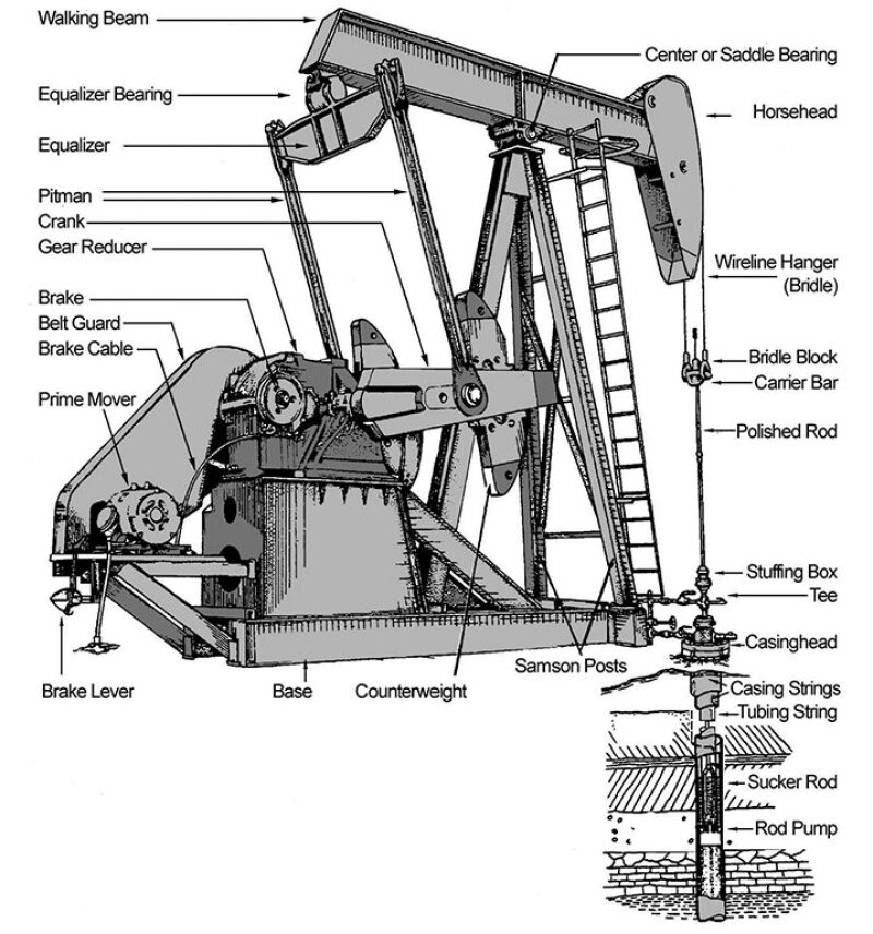
The Standard Rig Front and Sucker Rods
In 1886, writing in Petroleum and Its Products, Boverton Redwood describes a sucker-rod installation of his time: “The working barrel of the pump is placed at the bottom of the well on the end of the tubing, a perforated piece of casing of proper length, termed the ‘anchor,’ being attached to the lower end of the working barrel.
“To the sucker of the pump the required number of wooden sucker rods, screwed together, are attached, the upper end of the string of rods being connected with the walking beam. There is, of course, a valve at the bottom of the working barrel, and in the sucker. The sucker is provided with a series of three or four leather cups, which are pressed against the working barrel by the weight of the column of oil.”
From 1859, sucker rods were made of ash or hickory. Iron sucker rods were introduced in the late 1800s and carbon-steel box-and-pin rods in the early 1900s. With deeper and deeper wells being drilled and stepped-up pumping demands, the weight of the iron- or steel-rod string was recognized as a problem starting around 1917.
To offset this weight, composites were used in making rods, and hollow tubular rods were made. In 1923 one effort to minimize rod failures involved heat-treating rod ends. But full normalization, first done in 1927, was needed. Fully heat-treated steel sucker rods were commercially offered starting in 1930.
However, sucker rods remained a baffling problem. In a 1935 paper discussing sucker-rod materials’ corrosion-fatigue limits, Blaine B. Wescott and C. Norman Bowers state, “It is a rare occurrence in industry that the use of such a simple piece of equipment as a sucker rod presents so complicated a problem for solution.”
The Rise of the Beam-Pumping Unit
The hydraulic rotary drilling system started being developed and used during the final 3 decades of the 19th century—for drilling water wells and shallow oil wells in places where percussive (cable-tool) drilling could not effectively be used. Its usage rose following its first major success with the Spindletop well near Beaumont, Texas, in 1901, and modest improvements were made up to around 1915.
From 1915 to 1927 major changes were made to rotary-drilling equipment, but cable-tool percussive equipment—and the standard rig front—maintained its hold in the industry. The weight and power of cable-tool equipment increased during that period as wells became deeper.
John H. Suter states in a patent issued to him in October 1925, “In pumping deep wells, such as oil wells, a reciprocating pump is commonly used wherein mechanical motion is transmitted to the piston by means of a sucker rod. In such constructions, because of the great length of the sucker rod required, various difficulties are met with. Among these are stretching of the rod at each stroke, pulling apart of the rod, excessive wear on the rod in rubbing against the casing, weight of the parts to be moved, and buckling of the rod. These factors result in decreasing efficiency and breakage of parts.”
By 1932—with the evolution of efficient gear-reduction units, which, in turn, permitted the introduction of multicylinder, high-speed gas-engine prime movers, and with the development of efficient mobile well-servicing units, which eliminated the need to provide power and hoist at each well—the standard rig front had given way to beam-pumping units.
The Dynamometer: Understanding Rod-Pumping System Dynamics
Transmitting power using sucker rods continued to increase in geometric proportion to the greater depth to which wells were drilled. This led to groundbreaking analysis to understand the forces at work when an elastic rod system moved, or the loads transferred to the pumping mechanism.
In a seminal paper, “An Oil-Well Pump Dynagraph” (paper API-26-094), written in 1935, Walton E. Gilbert writes, “It has become increasingly obvious that the action of a pump a mile or more under ground cannot be accurately understood from observations made at the surface.”
In placing a dynamometer at the downhole pump, Gilbert proved conclusively that loss of displacement in wells located 5,000 ft or below the surface is generally not due to loss of stroke but often is attributable to ineffective separation of gas from the liquid pumped.
J.S. Montgomery, C.J. Coberly, J.C. Slonneger, and Emory Kemler each praised Gilbert’s paper, study, and the “ingenious instrument” for which “no doubt, many uses not now apparent will be found.”
In his 1937 paper, “Vibration Problems in Oil Wells” (paper API-37-139), J.C. Slonneger discusses the relationship between vibration and the contour of dynamometer cards. He develops a simplified method of calculating sucker-rod and cable-tool vibration frequencies, applies the method in developing a series of theoretical cards, and compares the theoretic cards with dynamometer cards from operating wells. The comparison confirms the theoretical method.
It was not until the early 1960s, when Sam Gavin Gibbs produced a derivation of the wave equation to model the elastic behavior of the rod string, that a dynamic model was developed that took into account behavior measured over a period of time—which is the reality captured in tracings on dynamometer cards. Based on the wave equation arising from Newtonian dynamics and Hooke’s law of elasticity, Gibbs’ derivation includes the effects of friction.
Gibbs’ work, amplified and broadened over the years, has permeated the industry and is used today both in diagnosing problems in existing installations and in predictive modeling for new installation design.
History: Gas Lift
Of all the types of petroleum lifting methods, gas lift is by far the oldest.
This might appear counterintuitive until one reads what Silas Frederick Shaw, pioneer consultant on vertical flow, wrote in 1927 in “Principles of the Air and Gas Lift” (Oil and Gas Journal), “[A] flowing well is a natural gas lift, in which the compressed gas is supplied by nature and is dissolved in, mixed with, or associated with, the oil in some form, and issues with the oil. It would be more accurate, perhaps, to say that the oil issues with the gas, since it is the movement of the gas through the sands and up through the casing that carries the oil with it. With the exception of wells caused to flow by hydrostatic pressure behind the oil, there would be no natural flowing of oil in wells if there were no gas associated with the oil.”
The insight to use natural gas to artificially control the flow of petroleum only gradually dawned on people as general understanding developed of gases—where and how they occurred, their flow behavior, and their effect on each other and on specific liquids and solids.
Beginnings: Air Lift
Throughout the 1800s, methods were continually being developed to artificially lift water from water wells. These were based on the work of German mining engineer Carl Emanuel Löscher (1750–1815), who had invented a means of using compressed air to pump liquids. In 1797, he conducted several laboratory experiments with his invention and published a description of it in a pamphlet titled Aerostatisches Kunstgezeug.
It appeared logical to adapt water-well air-lift methods for use in petroleum wells.
According to J.H.A. Bone (Petroleum and Petroleum Wells, 2nd ed.; Philadelphia: J.B. Lippincott & Co., 1865), compressed air was used as a way of lifting petroleum beginning with the Empire #1 well, the first “flowing” well (initially producing 3,000 B/D through natural flow) whose flow ceased in May 1862, 8 months after completion. Bone writes that a method of lifting petroleum from apparently depleted wells, “which is coming into use, and which has so far proved successful, is to use an ‘ejector,’ or air-pump, with two pipes inserted into the tube of the well. The air is forced down one pipe into the vein at the bottom, and the oil rushes up in a steady stream through the other. By the use of these ‘ejectors’ a number of wells have been restored to a yield ranging from thirty to a hundred and forty barrels daily, after they had been considered worthless by their owners.”
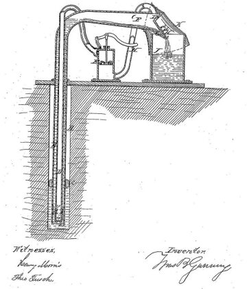
Thomas B. Gunning was issued a US patent on an “oil ejector for oil wells” on 22 November 1864. “This invention relates to a new and useful means for ejecting or forcing oil from oil-wells,” writes Gunning in his patent, “and is an improvement on the atmospheric pump recently employed for that purpose.”
Until around 1900, many engineer-inventors explored means of improving air lift in petroleum wells. Other engineers explored how air lift—in theory and in practice—applied to promoting the flow of water in water wells.
Although air lift was used, it was not understood. This required an understanding of what air is. This was in the process of being discovered during the petroleum era’s first several decades.
We understand now that Earth’s atmospheric air consists of several gases. There are steady concentrations, by volume, of nitrogen (78.084%) and oxygen (20.946%), along with far smaller concentrations (in descending order) of argon, neon, helium, methane, krypton, hydrogen, nitrous oxide, and xenon. The most significant gases present in variable concentrations, by volume, are water vapor, carbon dioxide, ozone, sulfur dioxide, and nitrogen dioxide.
However, air used for lifting oil was generally drawn from a petroleum well’s immediate vicinity. Therefore, close to the well, the percentage of gases normally present in atmospheric air would shift, as varying percentages of other gases flowed from the well and into the ambient atmospheric air. Gases also present in that ambient air might include petroleum vapors and natural gas’s component gases—mostly methane, with the possible presence of ethane, propane, butane, pentane, carbon dioxide, nitrogen, and/or hydrogen sulfide.
One could thus not predict how, at atmospheric pressure or under compression, the ambient air’s gases might interact with each other, with air-lift and other production equipment, or with the petroleum.
Transitioning From Air to Gas Lift
In the Texas and Louisiana coast fields, developed in 1901, “air-compressor plants were installed in the Gulf coast fields at Sour Lake, Evangeline, Humble, and elsewhere to furnish air to pump oil wells. … The air lift has been used continuously along the Gulf since then,” writes H.C. Miller, a US Bureau of Mines (USBM) petroleum engineer, in Gas-Lift Method of Flowing Oil Wells (California Practice), USBM Bulletin 323, 1930.
“For several years prior to 1911,” Miller states further, “the air lift was also used successfully in the Cat Canyon field, Santa Barbara County, California. During 1911 pumping tests were made that involved the use of high-pressure natural gas instead of air to stimulate the flow of oil from wells, and the author believes that these tests were the first in which natural gas was used to lift oil from wells.”
Throughout the middle and late 1920s, there was field experimentation with gas-lift equipment, parts of which were often designed and built “on the fly” and implemented without patent application; inventive development of patented gas-lift valves and systems; and examination on a theoretical level of the interplay between gas/oil ratios, oil gravities, and flow under varying temperature/pressure conditions.
By 1927, E.O. Bennett (Texas) and K.C. Sclater (Oklahoma), chief production engineers at Marland Oil Co., recognized that “One of the principal reasons for the oil industry’s slowness to adopt gas-lift methods is due to the poor results first obtained in trying to use methods of air lift for raising water in producing oil.”
Overall, the most commercially significant early advances were made between the early 1920s and the late 1950s. Alexander Boynton, J. Oliphant, Halbert B. Havorsen, James W. Taylor, Thomas E. Bryan, Herbert C. Otis, Charles S. Crickmer, Jeddy D. Nixon, and Henry Udell Garrett made the greatest number of gas-lift equipment improvements between 1923 and 1957, according to Coberly.
“The use of natural gas for flowing wells in place of air,” writes Coberly, “was a much more important development than the actual mechanical devices used in the gas-lift method. The use of gas not only reduced the hazards of the inflammable and explosive mixtures formed when air is used, but also made it possible to recover large quantities of gasoline [condensate] and LPG [liquid petroleum gas] that otherwise would have been wasted.”
Gas Lift: 1975–Present
In 1975, Buford Neely (Artificial Lift, SPE Reprint Series 12) defined the two types of gas lift in existence then and to this day: “Gas lift is a process of lifting fluids from a well by continuously injecting relatively high-pressure gas to reduce the flow gradient (continuous flow), or by injecting gas over a relatively short time period, beneath an accumulated liquid slug to move the slug to the surface (intermittent [flow]).”
Today, according to Herald Winkler and Jack Blann (“Gas Lift,” Petroleum Engineering Handbook, Vol. IV, SPE: 2007) the vast majority of gas-lift wells use continuous flow, which is very similar to natural flow.
Gas lift is used most successfully when a significant amount of gas is produced with the crude. In most cases, gas compressors are installed to gather the produced gas and, with minor changes, can be designed to supply the high injection-gas pressure for the gas-lift system. Most continuous-flow wells that have strong water drive can be truly depleted by gas lift.
In offshore installations, gas lift is widely used both from platforms and subsea, often at today’s deepest depths. Gas lift is also used for heavy-oil production.
Nitrogen and carbon dioxide are also sometimes used for gas-lifting crude oil. Air is still used to lift oil, but, because of the dangers, on a very limited scale.
History: Electrical Submersible (or Submergible) Pumps
The appearance of oil-production-related electrical submersible pumps (ESPs) coincided with developments in electrical power generation throughout the Western world, which began around 1880 and subsequently spread, giving rise to the regional power systems of the 1920s.
The first patent to show an oil-production-related electric-motor type pump was issued in 1894 to Harry W. Pickett. Patent no. 529,804 used a downhole rotary electric motor operating through a Yankee screwdriver device to drive a plunger pump.
The next ESP-related patent was not issued until 1918, for a progressive solenoid engine driving a reciprocating plunger pump. “Heretofore, in very deep wells the rod that is connected to the piston, and generally known as the ‘sucker’ rod, very often breaks on account of its great length and the strains imposed thereon in operating the piston,” states inventor Robert E. Newcomb in his US patent no. 1,287,078. “The present invention is designed to replace this rod and to locate the electro-magnetic engine or piston-actuating device directly within the well-casing or the well-barrel itself and locate it so that the armature of this engine is directly connected to the piston of the pump.”
Several patents were issued after that. But it was not until 1926 that the first patent for a commercial, operable ESP was issued—to ESP pioneer Armais Arutunoff. The cable used to supply power to the bottomhole unit was also invented by Arutunoff.
By 1930, Arutunoff’s original ESP inventions were being refined and offered by the Reda Pump Company. Reda ESPs were developed that could handle production rates at depths that exceeded the capacity of rod pumps by a factor of 2:1 to 3:1—5,000 B/D at 1,000-ft lift to 1,000 B/D at 7,000-ft lift.
Primarily invented by Arutunoff, other ESPs were developed to handle smaller volumes of fluid under high pressure, and to handle high volumes even when fluid levels were drawn down to a few feet from bottom.
Since Arutunoff’s initial inventions, ESPs have continued to be used to pump fluid volumes at high rates. Their operation is quiet, safe, and clean; they are often used offshore and in other environmentally sensitive areas.
Today’s ESP is part of a downhole unit, suspended by tubing. It consists of a multistage centrifugal pump (top) with either an integral intake or a separate, bolt-on intake; a seal-chamber section (middle); and a three-phase induction motor, with or without a sensor package. Electricity is delivered from a surface control unit to the motor through a three-phase power cable running down the tubing string and ESP unit.
History: Hydraulic-Pump Lift
There are two types of hydraulic pumps used today in petroleum artificial lift: reciprocating hydraulic piston pumps (either single-acting or double-acting) and jet pumps.
Hydraulic Piston Single- and Double-Acting Pumps
According to Coberly (1961), in the 18th century, during the steam engine’s early days, “[o]ne of the applications of the steam cylinder was to operate pumps by directly connecting the engine piston rod to that of the pump.” This was the basic idea upon which subsequent variants of hydraulic pumps were designed.
One of the earliest such variants was the Bull Cornish pumping engine of 1798, designed by William Bull and Richard Trevithick. According to Arthur M. Greene Jr. (Pumping Machinery, 2nd ed., 1919), “This type of engine is the one which remained in use longer than any other, as it was much simpler than that of Watt and had all of the elements of economy.” Trevithick and Bull made a direct-acting steam pump with the cylinder directly over the well. “A beam was attached to the pump rod,” writes Coberly, “to which weight was applied to balance the rod load.”
The first US patented variant of this type of pump, for use specifically in oil wells, was issued to Hiram W. Faucett and Alexander T. Comer in 1872. Faucett was issued another patent, in 1878, for an invention that improved the “steam-pump for oil-wells … whereby the heat radiated from the same and the exhaust-steam may be employed to prevent the accumulation of paraffine [sic], bitumen, or other solid hydrocarbons in the bore of the well.”
Some improvements were made in hydraulic oil-well pump design between 1887 and 1905, but a concerted effort was not made to devise commercially and widely operable hydraulic pumps until the 1920s.
Coberly states that Arthur G. Gage, with a number of significant patents issued to him between 1925 and 1953, “should be credited with being one of the real pioneers of hydraulic pumping” in the oil field.
Gage successfully field-tested his Gage pump at Santa Fe Springs, Los Angeles County, California, in June 1924. He, C.H. Williams, and L.M. Kellogg were issued a patent in 1925 for improvements to deep-well oil pumps. John H. Suter’s 1925 patent for a hydraulically operated deep-well pump was the first to show an insert-type pump attached to the inner tube. This allowed removal of the entire mechanism by pulling the inner tube only. Before that, all designs required pulling both strings of tubing to recover the pump, thus largely offsetting the advantages of hydraulic pumps over rod pumps.
A patent issued to Edwin B. Galbreath, Long Beach, California, in April 1927 was for the first double-acting hydraulic pump. Several such pumps were developed in the following years, three of which—in addition to Galbreath’s—proved operable in the field.
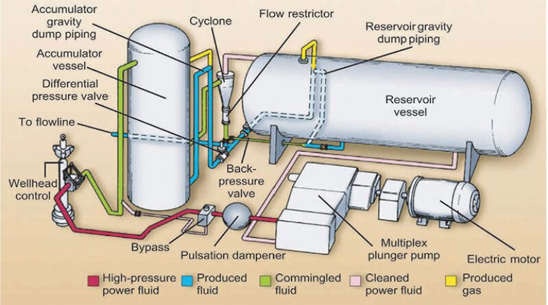
However, Coberly himself was the first to produce and successfully operate a fully balanced full double-acting pump. In a classic paper titled “Hydraulic Power Applied to Oil-Well Pumping” (API Petroleum World, 1935), Coberly describes a pump for which “[o]il is used as the hydraulic fluid. The equipment includes means for separating gas, water, and solids from the operating fluid and a pump for supplying fluid under high pressure. The sub-surface unit is a reciprocating engine direct-connected to a double-acting reciprocating pump. The unit is carried by a macaroni string of tubing and inserts within the regular production tubing.”
The type of pumping system Coberly describes is called a “fixed-insert” installation.
In separate patents issued in 1941, Coberly and Gordon Swain introduced one of the most significant advantages of hydraulic pumping systems—“free-pump” installations.
As explained by James Fretwell (Petroleum Engineering Handbook, Vol. IV; SPE: 2007), “Free-pump installations permit circulating the pump to the bottom, producing the well, and circulating the pump back to the surface for repair or size change.”
By the early 1970s, hydraulic pumping was widely used, especially in deep, high-volume pumping.
Jet Pumps
Fretwell (2007) notes, “The most significant feature of [a jet pump] is that it has no moving parts; the pumping action is achieved through energy transfer between two moving streams of fluid.” Jet pumps can be adapted to fit into the same bottomhole assembly used for hydraulic reciprocating piston pumps.
With different nozzles and throats, jet pumps can produce wells at less than 50 B/D or in excess of 15,000 B/D. Installation design calculations are complex and iterative in nature, requiring computer modeling. Energy efficiency is low. However, jet pumps are reliable, require little maintenance, and have unique volume capacities. Since their commercial introduction in the 1970s, their use has increased.
History: Progressing Cavity Pumps
Progressing cavity pumps (PCPs) are based on a gear mechanism invented by René Joseph Louis Moineau (1887–1948). Moineau’s second patent, issued in 1937, states it is for “a gear mechanism adapted for use as a pump, compressor, motor, or simple transmission device, and even, simultaneously, for several such uses.”
The idea has its roots in a pump for lifting water called the Archimedean screw. Invented by Archimedes (287–212 BCE), it was originally used for irrigation in the Nile delta and for pumping water out of ships.
The petroleum industry uses the Moineau mechanism for artificial lift as well as for downhole mud-motors that drive the bit.
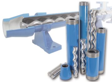
With the concurrent development of synthetic elastomers and adhesives, a PCP was introduced in 1936 for use in the petroleum industry. The downhole PCP is a positive displacement pump consisting of two parts: a helical steel rotor connected to the bottom of the rod string and a fixed stator that is run in to the well on the bottom of the production tubing. The stator consists of an elastomeric shape formed with a multiple internal helix matched appropriately to the rotor configuration. When the surface drive system rotates the rod string, the rotor spins within the fixed stator. This creates the pumping action.
The most common oil industry PCP system is surface-driven and includes the downhole pump; sucker-rod and production-tubing strings; and surface equipment, which includes a stuffing box, wellhead drive, prime mover, and flowline. PCPs can also be driven by an electrical-submersible or downhole hydraulic motor.