
The elliptical (conical) damage profile associated with horizontal wells is well-known, but review of industry-wide applications by different operators shows no corresponding uniform correlation between the damage profile and actual treatment volumes that have been applied. This inadequacy has often led to suboptimal post-stimulation performances. Furthermore, funds spent on stimulating horizontal wells did not yield the expected rewards; the stimulation gains are mostly short-lived because of flawed volume design and application.
Introduction
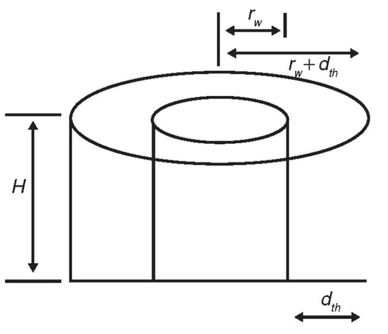
Unlike the vertical-well-damage profile, the damage profile around a horizontal wellbore is neither radial nor distributed evenly along its entire length because of formation anisotropy that creates an elliptical damage profile normal to the wellbore. The exposure time to fluids during drilling and completion operations, or the varying magnitude of fluid flow quantities across the various segments of the drainhole length during the production and injection process, will result in a truncated elliptical cone of damage along the length of the well, representing a frustum (Fig. 1) with the base of the cone nearest to the heel (near the vertical section of the wellbore).
Fluid diversion is often difficult to achieve in horizontal wells because fluids tend to take the path of least resistance, even when using mechanical diverting aids or coiled tubing. Considering the fact that large quantities of acid are required for matrix stimulation of horizontal sections, it is often desirable to assume partial damage removal, but this often results in the creation of a stimulated zone with improved permeability surrounded by a collar of damage. Notwithstanding these challenges, effective distribution of the stimulation fluid along the entire length of the well is desirable, and this is why a consideration of the nature of the damage distribution in horizontal wells is very important and key to achieving a true stimulation.
In order to address this first step in horizontal-well-stimulation fluid design, a model development was carried out to simultaneously determine the acid volume required to cover the damage area of the horizontal near-wellbore region and each of the segments as desired on the basis of operational feasibilities.
The required input parameters for the new model are the drainhole length, the number of desired treatment segments, average porosity, wellbore radius, and estimated damage radius at the heel. The output parameters from the model include the acid volume required to treat each segment of the drainhole, which decreases from the heel toward the toe in conformance with the established elliptical damage profile.
Theoretical Background
The mathematical expression of the volume of a cone is the product of the area of the base and the perpendicular height. If a cone is cut by a plane parallel to its base, the portion of a solid between this plane and the base is referred to as a frustum of a cone (Fig. 2), and this is the identified shape of the damage in horizontal wells around the drainhole, with the drainhole representing a cylinder inside the frustum with a common center through which the symmetrical axis passes. For a series of equations that determines the frustum, cylindrical-shape volume, and damage area, please see the complete paper.
Damage Collar
During stimulation with coiled tubing, the volume of acid injected into each section of the near-wellbore region is dependent on the rate of coiled-tubing withdrawal and the injection rate at the prevailing run-in-hole or pull-out-of-hole speed. The shape of the damage profile is key to determining the appropriate volume of acid to completely remove the damaging materials in the near-wellbore region without leaving excessive acid strength that will deconsolidate the formation. For sandstone reservoirs, the stimulation-fluid volume should consider the shape of the damage cone with relationship to porosity, while for carbonate reservoirs, the profile should be dendritic (outside the scope of the present work) with relationship to expected wormhole porosity. When excess acid volume is injected, there is danger of stimulating undamaged zones and of possible near-wellbore formation deconsolidation with compressed permeability. This is because of possible collapse of the framework of quartz as a result of weakened cementacious material that binds the rock framework together. On the other hand, if insufficient acid volume is injected, the result will be a partial stimulation of some zones, with unstimulated zones shielding them in what is referred to as a damage collar, thereby preventing beneficial stimulation activity.
In either of these scenarios, the post-stimulation-activity well performance is predominantly a failure because production gains, if any, are not sustained. In order to circumvent this poor result, a more-realistic volume requirement and placement method must be considered to deal with the identified damage profile.
Analytical-Model Development
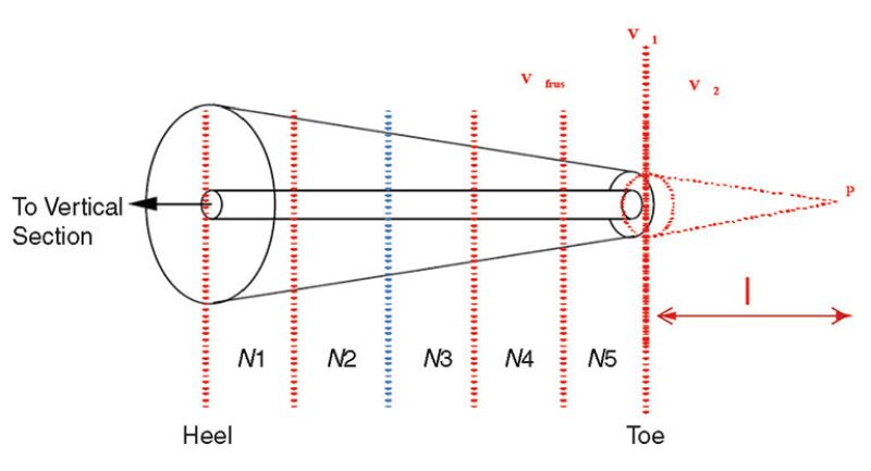
In an attempt to calculate the volumes of the connected voids of the matrix at different zones across the drainhole, equal segmentation of the horizontal length was introduced.
The number of segments for each design depends on what is practically possible to implement operationally (say, two to 10 segments, depending on the drainhole length and tools being deployed), but in practice, two to five segments are sufficient.
Value of the New Approach
- Stated simply, there is no uniformity among different operators in volumetric estimation and in the approach to truly removing damaging materials in the near-wellbore region of horizontal wells. This model attempts to bridge this gap because it offers the desired estimation of the volume of acid required to stimulate horizontal wells.
- Most often, the treatment acid comes back to the surface (as the so-called spent acid) in unspent condition, signifying that the quantity injected was more than the acid required to target the damaging materials or that the targeted damaging materials were not fully contacted by the acid. If such acid stays long in the formation, it will start to react with the binding cementacious materials, and this will often result in formation deconsolidation and compaction of the flow path (reduced permeability with attendant poor inflow). Adequate acid volume/concentration helps to eliminate this risk.
- In the event of excessive-acid-volume design, secondary precipitates may occur if the carbonaceous materials stay in prolonged contact with the unspent acid (particularly in the case of hydrofluoric acid), and this is why there could be initial post-stimulation gain that is not sustained.
- The new approach will offer selective stimulation where production hot spots exist in horizontal drainholes by directing acid treatments to where they are desired, meaning that there is no application of an inadequate acid volume, and more opportunity for improved stimulation performance in horizontal wells.
Challenges in Field Application
In a laboratory environment, the damage profile and the extent (thickness) of damage at each point across the drainhole can be visualized and measured, which further validates the previous observations regarding the elliptical damage profile in horizontal wells. The damage is highest at the heel and narrows down to zero at the toe. The engineering explanation of this phenomenon is that during the drilling, completion, injection, and production stages, the heel region sees more of these fluids, and the associated particles that constitute the damaging materials are present in greater quantity around the heel when compared to the toe; therefore, more deposition usually occurs around the heel.
In practical terms (existing wells), it is difficult to measure the extent of damage at every point across the drainhole, but the established damage profile remains valid. For vertical wells, it is known that the deep damage resides within 2–4 ft, moderate damage resides within 0.5–2 ft, and shallow damage resides within 0.5 ft in the near-wellbore region. In a like manner, it is believed that the deepest damage in horizontal wells lies below 2 ft, but most estimates assume 1-ft thickness. The key message of this work is that damage thickness is not uniform across the entire length. Whether 2, 1, 0.5, or 0.1 ft is assumed for the damage thickness at the heel depends on the engineer’s judgment based on his or her knowledge of the well (produced/injected fluids, formation mineralogy/lithology, and available data from production-logging tools). Some production-logging-tool runs have shown that the extent of damage at specific points can be investigated. However, in the absence of hard data about damage thickness, 1 ft can be assumed. Comparison of the strengths of the acid injected into the formation and the (spent) acid returned to the surface in relation to post-stimulation performance is commonly used to evaluate the treatment effectiveness and, of course, the correctness of the radius accessed by the treatment-acid volumes in both vertical and horizontal wells.
Field-Application Guide
When the choice of treatment-fluid-placement method is coiled tubing, the rate of coiled-tubing withdrawal and the rate of fluid pumped into each section of the hole will determine the volume of fluid injected and should take into account the identified shape of the damage cone present. Treatment is better when commenced from the toe toward the heel because there is better control when coiled tubing is pulled out of hole on the horizontal section.
The type of formation to be stimulated affects the damage shape in horizontal wells; for instance, in sandstones, the stimulation-fluid injection should mimic the shape of the damage cone, with acid volumes and tubing-withdrawal rates being closely related to porosity, while for carbonate reservoirs, the stimulation profile under matrix conditions will be dendritic, with a wormhole network extending radially from the wellbore. In this case, the volume of acid and withdrawal rate of the coiled tubing will be related to the expected radial wormhole porosity created.
If the bullhead technique is chosen for intervals greater than 50 ft for any reason (these are usually less effective than coiled-tubing application), diversion should be considered while placing the treatment starting from the heel and advancing toward the toe, because this will allow even distribution; however, it should be noted that the bullhead technique in horizontal wells has a low chance of success. In the absence of coiled-tubing treatment, straddle packers are an alternative where feasible.
This article, written by JPT Technology Editor Chris Carpenter, contains highlights of paper SPE 165143, “Development of a Volumetric Horizontal-Well-Stimulation Model,” by Linus A. Nwoke, SPE, Shell Petroleum Development Company of Nigeria, prepared for the 2013 SPE European Formation Damage Conference and Exhibition, Noordwijk, the Netherlands, 5–7 June. The paper has not been peer reviewed.