Artificial lift is a technique used to provide energy to the formation fluids in a production well when the pressure of the formation is not high enough for hydrocarbons to flow up the tubing string at an economic rate. Several types of artificial lift can be used to increase the production rate and maximize hydrocarbon recovery. The major artificial lift technologies are beam pumping/sucker rod pumps (rod lift), progressive cavity pumps, hydraulic submersible pumps, electric submersible pumps, and gas lift.
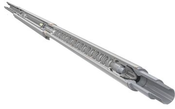
Hydraulic submersible pumps (HSPs) (Fig.1) are hydraulic turbine-driven downhole pumps that were developed as an alternative to the more commonly used electric motor-driven submersible (centrifugal or progressive cavity) pumps (ESPs). ESPs are used extensively in oil lift applications—particularly offshore. These pumps can experience failures attributable to the following:
- Exceeding the limits they were designed to operate within
- Electrical insulation failure in the wet well environment
- Sub-optimal field practices
- Overheating of the downhole electric motor
Particularly in the case of high operating-expense (OPEX) environments such as subsea wells, faced with increasing demand for ever-depleting resources, and the challenges associated with oil and gas production in increasingly difficult locations, there is a strong drive to maximize hydrocarbon recovery and lower operating costs through improvements in well pump technology. HSP technology has demonstrated a step change in pump mean time to failure (MTTF), validated through more than 13 years of subsea field operating experience. This presents a viable alternative for operators can consider to help improve their OPEX profiles through the use of a high-integrity engineered pumping solution.
How Does an HSP Work?
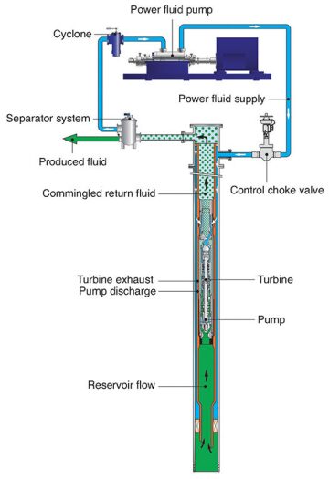
A turbine-driven HSP is powered by pressurised power fluid supplied from pumps on the surface. The high-pressure power fluid flows down a dedicated supply flowline and enters the tree at a controlled pressure and flow rate. In the most common “open loop” configuration, the power fluid enters the HSP through the well annulus and de-pressurises through the multistage, axial flow turbine, providing the drive to the pump end to boost the pressure of the formation fluids, (Fig. 2). The produced fluid at pump discharge subsequently commingles with the exhausted turbine power fluid and flows up through the production tubing, flowline, and riser to the surface facilities. At this point, the power fluid is then separated, filtered, and recirculated back into the HSP power fluid supply and water disposal system. Another option is to supply power fluid in a “closed loop,” where the power fluid does not commingle with the formation fluids. Although this is a more complex completion design, with two concentric annuli required for the independent supply and return of power fluid, it minimizes the load on the primary oil/ water separation facilities.
HSP Differentiators
An HSP differs from other artificial lift technologies due to a number of factors:
Wide Operating Envelope—The power fluid supply not only drives the turbine but provides a hydrostatic pressure feed to the radial and axial bearing system, meaning that the inherently variable speed rotor is well supported under all operating conditions including gassy, sandy, or viscous fluids.
High Speed and Compact Assembly—The turbine design and bearing support systems enable operation at super synchronous speeds (typically 5,000 to 10,000 rpm). These operating speeds are significantly greater than those of a comparable ESP, thus providing a greatly reduced pump stage bundle length, resulting in a compact, easily deployed assembly.
Elimination of Traditional Failure Modes—Rather than relying on full isolation of the drive section from the well fluids through the use of mechanical seals and protectors, the power fluid used to drive the turbine provides a positive, outward clean flush to the pump end bearing system and is a key life-enhancing feature. In addition, an HSP is assembled on a single, high-precision shaft, eliminating the need for motor-pump coupling at the well site.
Advanced Materials of Construction—Components consisting of high-end materials maximize an HSP’s operational life. Such materials include super duplex stainless steels, ceramics, and nickel/cobalt alloys that, over extended time periods, provide excellent resistance to erosive and abrasive wear, corrosion, and sour service.
An HSP provides benefits for the production of formation fluids, particularly in challenging applications such as:
Heavy Oil Applications—Viscosity management is a major flow assurance challenge associated with heavy oils, more so if there is an emulsion-forming tendency that could significantly increase fluid gross viscosity. With an “open loop” power fluid supply configuration, formation fluids with high viscosity are commingled with the power fluid to achieve a water-continuous dispersion downstream of the HSP, which subsequently reduces associated friction losses.
Multiphase Pumping—Producing oil wells often encounter multiphase mixtures, either by design or unintentionally, as free gas is often co-produced. The presence of free gas at pump suction can adversely affect the hydraulic performance of pumps, which are generally designed to handle incompressible fluids.
Methods of handling gassy fluid streams have traditionally included pump suction gas-liquid separators and variable-speed controllers to minimize gas ingestion and avoid gas locking and overheating of the motor.
Recent developments have seen the incorporation of special helico-axial or mixed-flow impellers to increase the maximum gas void fraction before gas locking occurs. However, despite these advances, today’s extensive use of horizontal wells that can generate sluggy multiphase flow regimes continues to threaten the availability and reliability of downhole motor-driven machines.
In contrast, in addition to having helico-axial design multiphase impellers, an HSP’s constant power turbine drive provides an inherently variable speed operating capability when it encounters variable-density fluids within the pump end. For a given power input, the rotor will speed up and gas compression efficiency will improve in response to increased gas void fraction.
In addition, even when faced with a 100% gas slug event, the interstage hydrostatic bearings and thrust-balancing arrangement are continuously fed with power fluid, which increases the liquids-to-gas ratio through the pump whilst still supporting the rotor in the radial and axial direction.
Wax, Scale, and Corrosion Management—Wellbore chemical treatments are often required during production to overcome problems encountered with waxing, scaling, or corrosion. In these scenarios, chemicals must to be injected into the production fluid path via dedicated flowlines. With HSP, such inhibitors can be added through power fluid supply at the surface facility.
Similarly, heated power fluid can be utilized to artificially increase the temperature of the commingled produced fluid to guard against gelling in fluids with low wax-appearance temperatures.
The functionality of the open loop HSP power fluid system provides the capability to circulate out hydrocarbons from all flow paths above pump setting depth, thus mitigating against cold fluid legs that could cause re-start issues.
System Requirements
The design and arrangement of the power fluid system is almost as important as the design of an HSP itself—to ensure that consistently high-quality drive fluid is delivered to the machine. An HSP can make use of many of the water processing elements commonly found in oilfield facilities, including separators, filters/cyclones, and high-pressure pumping systems.
Conventional, high-reliability pumps are used at the surface to generate pressurized drive fluid, and operational control is effected by a combination of variable speed pump drive motors and individual well tuning by use of choke valves locally at the tree. Typically, a single-power water pump will be installed in order to drive up to four HSPs. The use of readily serviceable, conventional water processing systems as a motive source thus provides an opportunity for improved lift system functionality, availability, and reliability.
Field Applications
The simplicity and flexibility of an HSP has been instrumental in its application to a broad range of artificial lift duties, including onshore and offshore applications, multiphase pumping of heavy oil, aquifer lift, and seabed (mudline) boosting, as well as on thermal production applications, such as steam-assisted gravity drainage.
In recent times, multiphase HSPs have been successfully applied to subsea, wet tree production of gassy, heavy oil in Chevron’s Captain field in the UK North Sea. The subsea area of this field has been exclusively produced using HSP technology, with the pumps having achieved an MTTF of over 11 years and a 170-year cumulative operational time.
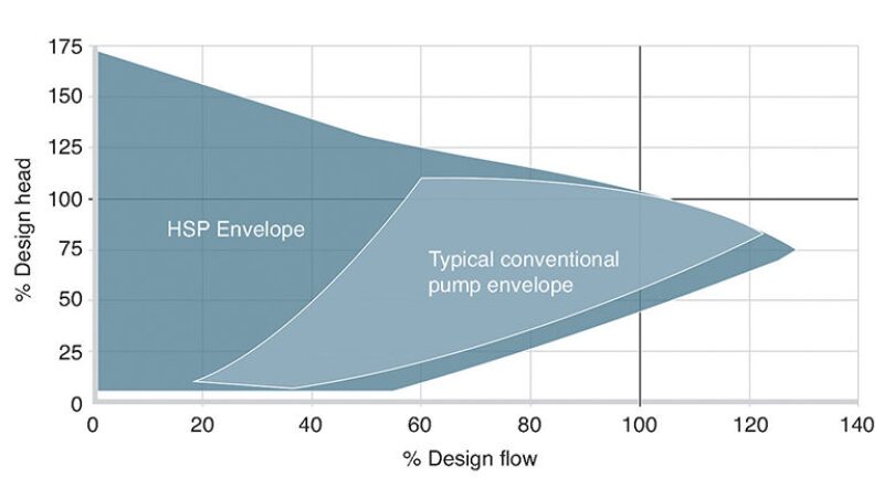
Field data indicate the successful operation of an HSP on suction gas void fractions in excess of 70%, illustrating the excellent gas handling capability achieved by the combination of helico-axial impeller design and turbine drive. The HSP bearing system provides a wide operating range which enables the well to be produced without distressing the pump. Fig. 3 shows the range of HSP operating points for a single pump achieved on a typical well.
For thermal production operations, the HSP has been designed and qualified to operate at fluid temperatures of up to 220°C in standard trim. Higher-temperature applications can be accommodated through changes to sealing element materials.
Abhishek Bhatia, a mechanical engineer at SPX, is primarily responsible for assessing hydraulic submersible pumps’ (HSPs’) appropriateness in different applications by engaging early with endusers or field development consultants. His current role also includes carrying out detailed hydraulic studies, well modeling, selecting optimum HSP configuration during pre-FEED and FEED stages, and mechanical design. In his previous role, he was involved with the design and packaging of surface pumps, typically used for water injection, crude export, and seawater-lift applications. He holds a BEng (Hons.) degree in aero-mechanical engineering from the University of Strathclyde and an MSc degree in design of rotating machines from the Cranfield University.
Scott McAllister is a mechanical engineer at SPX, responsible for engineering design of high-power downhole and subsea pumping systems within the engineered solutions team at ClydeUnion Pumps, part of SPX. Since joining the company in 2008, he has completed engineering development work, ranging from conceptual design through to the definition of detailed design scopes. McAllister attends offshore production and drilling facilities to supervise the installation of hydraulic submersible pumps. He holds a BEng (Hons.) degree in product design engineering from the University of Glasgow and the Glasgow School of Art and an MSc degee in mechanical engineering (design) from Glasgow Caledonian University.